THE 8086 MICROPROCESSOR
THE 8086 MICROPROCESSOR. The 8086 Microprocessor. The 8086, announced in 1978, was the first 16-bit microprocessor introduced by Intel Corporation 8086 is 16-bit MPU.


THE 8086 MICROPROCESSOR
E N D
Presentation Transcript
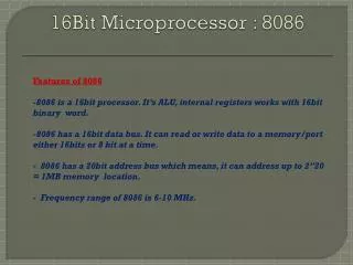
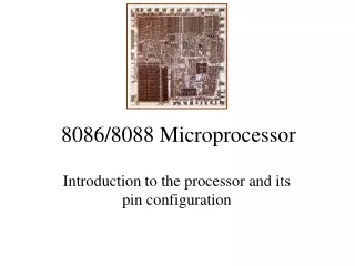
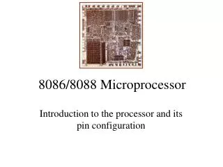
The 8086 Microprocessor • The 8086, announced in 1978, was the first 16-bitmicroprocessor introduced by Intel Corporation • 8086 is 16-bit MPU. • Externally the 8086 has a 16-bit data bus8086 has the ability to address up to 1 Mbyte of memory and 64K of input/output port • The 8086 is manufactured using high-performance metal-oxide semiconductor (HMOS) technology • The 8086 is housed in a 40-pin dual inline package and many pins have multiple functions
Architecture of 8086 • The architecture of 8086 includes • Arithmetic Logic Unit (ALU) • Flags • General registers • Instruction byte queue • Segment registers
EU & BIU • The 8086 CPU logic has been partitioned into two functional units namely Bus Interface Unit (BIU) and Execution Unit (EU) • The major reason for this separation is to increase the processing speed of the processor • The BIU has to interact with memory and input and output devices in fetching the instructions and data required by the EU • EU is responsible for executing the instructions of the programs and to carry out the required processing
Execution Unit • The Execution Unit (EU) has • Control unit • Instruction decoder • Arithmetic and Logical Unit (ALU) • General registers • Flag register • Pointers • Index registers
Execution Unit • Control unit is responsible for the co-ordination of all other units of the processor • ALU performs various arithmetic and logical operations over the data • The instruction decoder translates the instructions fetched from the memory into a series of actions that are carried out by the EU
Execution Unit - Registers • General registers are used for temporary storage and manipulation of data and instructions • Accumulator register consists of two 8-bit registers AL and AH, which can be combined together and used as a 16-bit register AX • Accumulator can be used for I/O operations and string manipulation
Execution Unit - Registers • Base register consists of two 8-bit registers BL and BH, which can be combined together and used as a 16-bit register BX • BX register usually contains a data pointer used for based, based indexed or register indirect addressing • Count register consists of two 8-bit registers CL and CH, which can be combined together and used as a 16-bit register CX • Count register can be used as a counter in string manipulation and shift/rotate instructions
Execution Unit - Registers • Data register consists of two 8-bit registers DL and DH, which can be combined together and used as a 16-bit register DX • Data register can be used as a port number in I/O operations • In integer 32-bit multiply and divide instruction the DX register contains high-order word of the initial or resulting number
Execution Unit - Flags • Overflow Flag (OF) - set if the result is too large positive number, or is too small negative number to fit into destination operand • Direction Flag (DF) - if set then string manipulation instructions will auto-decrement index registers. If cleared then the index registers will be auto-incremented • Interrupt-enable Flag (IF) - setting this bit enables maskable interrupts • Single-step Flag (TF) - if set then single-step interrupt will occur after the next instruction
Execution Unit - Flags • Sign Flag (SF) - set if the most significant bit of the result is set. • Zero Flag (ZF) - set if the result is zero. • Auxiliary carry Flag (AF) - set if there was a carry from or borrow to bits 0-3 in the AL register. • Parity Flag (PF) - set if parity (the number of "1" bits) in the low-order byte of the result is even. • Carry Flag (CF) - set if there was a carry from or borrow to the most significant bit during last result calculation
Execution Unit - Pointers • Stack Pointer (SP) is a 16-bit register pointing to program stack • Base Pointer (BP) is a 16-bit register pointing to data in stack segment. BP register is usually used for based, based indexed or register indirect addressing. • Source Index (SI) is a 16-bit register. SI is used for indexed, based indexed and register indirect addressing, as well as a source data addresses in string manipulation instructions. • Destination Index (DI) is a 16-bit register. DI is used for indexed, based indexed and register indirect addressing, as well as a destination data addresses in string manipulation instructions.
Bus Interface Unit • The BIU has • Instruction stream byte queue • A set of segment registers • Instruction pointer
BIU – Instruction Byte Queue • 8086 instructions vary from 1 to 6 bytes • Therefore fetch and execution are taking place concurrently in order to improve the performance of the microprocessor • The BIU feeds the instruction stream to the execution unit through a 6 byte prefetch queue • This prefetch queue can be considered as a form of loosely coupled pipelining
BIU – Instruction Byte Queue • Execution and decoding of certain instructions do not require the use of buses • While such instructions are executed, the BIU fetches up to six instruction bytes for the following instructions (the subsequent instructions) • The BIU store these prefetched bytes in a first-in-first out register by name instruction byte queue • When the EU is ready for its next instruction, it simply reads the instruction byte(s) for the instruction from the queue in BIU
Segment: Offset Notation • The total addressable memory size is 1MB • Most of the processor instructions use 16-bit pointers the processor can effectively address only 64 KB of memory • To access memory outside of 64 KB the CPU uses special segment registers to specify where the code, stack and data 64 KB segments are positioned within 1 MB of memory
Segment: Offset Notation • A simple scheme would be to order the bytes in a serial fashion and number them from 0 (or 1) to the end of memory • The scheme used in the 8086 is called segmentation • Every address has two parts, a SEGMENT and an OFFSET (Segmnet:Offset ) • The segment indicates the starting of a 64 kilobyte portion of memory, in multiples of 16 • The offset indicates the position within the 64k portion • Absolute address = (segment * 16) + offset
Segment Registers • The memory of 8086 is divided into 4 segments namely • Code segment (program memory) • Data segment (data memory) • Stack memory (stack segment) • Extra memory (extra segment)
Different Areas in Memory • Program memory – Program can be located anywhere in memory • Data memory – The processor can access data in any one out of 4 available segments • Stack memory – A stack is a section of the memory set aside to store addresses and data while a subprogram executes • Extra segment – This segment is also similar to data memory where additional data may be stored and maintained
Segment Registers • Code Segment (CS) register is a 16-bit register containing address of 64 KB segment with processor instructions • The processor uses CS segment for all accesses to instructions referenced by instruction pointer (IP) register • Stack Segment (SS) register is a 16-bit register containing address of 64KB segment with program stack • By default, the processor assumes that all data referenced by the stack pointer (SP) and base pointer (BP) registers is located in the stack segment
Segment Registers • Data Segment (DS) register is a 16-bit register containing address of 64KB segment with program data • By default, the processor assumes that all data referenced by general registers (AX, BX, CX, DX) and index register (SI, DI) is located in the data segment • Extra Segment (ES) register is a 16-bit register containing address of 64KB segment, usually with program data • By default, the processor assumes that the DI register references the ES segment in string manipulation instructions
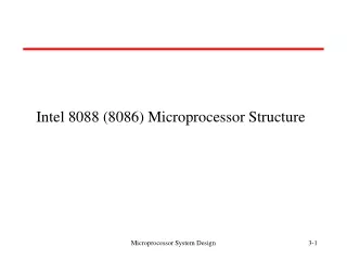
The 8086 Microprocessors Pin layout of the 8086 microprocessor
Electrical Characteristics • Power is applied between pin 40 (Vcc) and pins 1 (GND) and 20 (GND) • The nominal value of Vcc is specified as +5V dc with a tolerance of ±10%. • Both 8088 and 8086 draw a maximum of 340mA from the supply I/O voltage levels
Bus Cycle and Time States • A bus cycle defines the basic operation that a microprocessor performs to communicate with external devices. • Examples of bus cycles are the memory read, memory write, input/output read, and input/output write. • The bus cycle of the 8088 and 8086 microprocessors consists of at least four clock periods. • If no bus cycles are required, the microprocessor performs what are known as idle states. • When READY is held at the 0 level, wait states are inserted between states T3 and T4 of the bus cycle.

![8086 [2]](https://cdn1.slideserve.com/2457127/8086-2-dt.jpg)