Download

1 / 20
270 likes | 562 Views
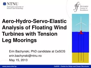
Aero-Hydro-Servo-Elastic Analysis of Floating Wind Turbines with Tension Leg Moorings. Erin Bachynski, PhD candidate at CeSOS erin.bachynski@ntnu.no May 15, 2013.

E N D
Aero-Hydro-Servo-ElasticAnalysisofFloating Wind TurbineswithTension Leg Moorings Erin Bachynski, PhDcandidate at CeSOS erin.bachynski@ntnu.no May 15, 2013 www.cesos.ntnu.no CeSOS – Centre for Ships and Ocean Structures
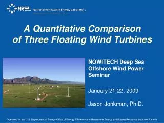
Floatingwindturbineconcepts studied at CeSOS We need to understand floating wind turbine behavior so that we can bring the cost down Spar Semi-submersible TLP
Tension Leg Platform (TLP) • Stability from tension legs, implying motions as an inverted pendulum • Small motions (+) • Flexible w.r.t. water depth (+) • Smaller steel weight (+) • Small footprint area on seabed (+) • Challenging installation (-)
TLPWT Design Moon, 2010 • Displacement • Increasescost • Decreases risk ofslack • Pontoon radius • Increasesstability • Increases hull loads • Tendons Shimada, 2011 MIT-NREL TLPWT (Matha, 2009) Botta, 2009
Integratedaero-hydro-servo-elasticanalysis control aerodynamics structural dynamics Challenges: -complexity -tightcoupling -nonlinear -time domain -long term periods -transient (faults) hydrodynamics Source: NREL/Wind powertoday, 2010.
Aerodynamics J. de Vaal, 2012
Control system • Serves to • regulate rotor rotation speed • regulate power output • protect structure • Actions • Change generator torque • Change blade pitch
Blade pitch mechanism failures Contribution to failure rate (failures/turbine/yr) (%) Jiang, 2012 PhD candidates at CeSOS studying the effects of control system failures on different platforms : Z. Jiang, M. Etemaddar, E. Bachynski, M. Kvittem, C. Luan, A. R. Nejad Pitch system Wilkinson et al., 2011
What happens if one blade stops pitching? TLP, U=20m/s, Hs = 4.8m, Tp = 10.8s Continue operating with faulted blade Fault occurs Shut down turbine quickly
Comparison of controller fault effects on different platforms Semi-Sub 1 Semi-Sub 2 Spar TLP
Environmental/Fault Conditions Max. thrust 50 yr. storm Ext. turb. * Simulation length after 200s initial constant wind period
No fault Blade seize Blade seize + shutdown Grid loss + shutdown Storm condition Extreme turbulence at rated speed Tower Top FA Bending Moment
Hydrodynamics aerodynamics control • Large volume structures: potential flow • First order • Second order sum-frequency • Slender structures: Morison’s equation • Tension-moored structures: ringing forces (3rd order) hydrodynamics
Structural Modeling aerodynamics control structural dynamics hydrodynamics Flexible beam elements (tower, blades, mooring system) Rigid hull Global model – simplified generator
Pitch TLPWT Parametric Design Study: • Diameter • Water Depth • Pontoon Radius • Ballast Fraction • 45 resulting designs • 7 environmental conditions Tower Base Bending Line Tension
Concluding remarks • TLP wind turbines present complex, unanswered design and analysis challenges • Numerical simulations require coupled aero-hydro-servo-elastic tools and expertise • A wide variety of environmental and operational conditions must be considered • In our studies of floating wind turbines at CeSOS we hope to provide insights that can help inform designers and regulatory bodies
TLPWT + 3 Point Absorbers • Preliminary results indicate no significant change in power output for WEC or WT by combining • Reduced tendon tension variation (5-10%) and motions % difference calculated as [(TLPWTWEC) – TLPWT]/TLPWT
Simo-Riflex-AeroDyn Java: control AeroDyn: aerodynamic forces • Nonlinear time domain coupled code (Riflex: MARINTEK) • Single structural solver • Aerodynamic forces via DLL • Advanced hydrodynamics (Morison, 1st and 2nd order potential, ringing) (SIMO: MARINTEK) • Control code (java) for normal operation and fault conditions • Good agreement with HAWC2 (land-based and spar, including fault) SIMO: wave forces Riflex: structural deflections, time stepping