Download
1 / 24
240 likes | 457 Views
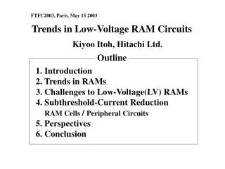
FTFC2003, Paris, May 15 2003. Trends in Low-Voltage RAM Circuits. Kiyoo Itoh, Hitachi Ltd. Outline. 1. Introduction 2. Trends in RAMs 3. Challenges to Low-Voltage(LV) RAMs 4. Subthreshold-Current Reduction RAM Cells / Peripheral Circuits 5. Perspectives 6. Conclusion. 16 G. 10,000.

E N D
FTFC2003, Paris, May 15 2003 Trends in Low-Voltage RAM Circuits Kiyoo Itoh, Hitachi Ltd. Outline 1. Introduction 2. Trends in RAMs 3. Challenges to Low-Voltage(LV) RAMs 4. Subthreshold-Current Reduction RAM Cells / Peripheral Circuits 5. Perspectives 6. Conclusion
16 G 10,000 Full CMOS ISSCC/VLSI Stand-alone RAMs ISSCC/VLSI Stand-alone RAMs 1 G 1,000 Poly-Si load 64 M 72 Planar capacitor 32 100 18 DRAM DRAM Memory Capacity/chip (bits) Memory Cell Area (mm2) Full CMOS TFT load 4 M 10 3-D capacitor 256 K SRAM SRAM 1 16 K 0.1 1 K 2000 1990 1970 1980 2000 1990 1970 1980 Year Year Trends in RAM Developments (R&D) K. Itoh, VLSI Memory Chip Design, Springer-Verlag, March 2001 K. Itoh, Hitachi
DRAM SRAM VDD Qs = Cs VDD/2 Qs = Cs VDD/2 WL VDD Cs WL DL 1 " " DL DL 0 Cs " " 0 VDD 0 (0) (VDD) stand-aloneRAM / e-RAM RAM cell array DRAM SRAM periph. Challenges to LV RAMs RAM Cells Leakage Reductions Tunnel Current Subthreshold Current Shorter tREFmax(DRAM) Larger retention current (SRAM) Stable Operations Peripheral Circuits Leakage Reductions Compensation for speed variations due to design parameter variations / VT / (VDD –VT0), VT =VT0 (mean) + VT, Stringent control of VT Compensations forVTwith internal control of VDD / VSUB Reduced Qs (= CsVDD / 2) SER Ever-increasing VT / VT K. Itoh, VLSI Memory Chip Design, Springer-Verlag, March 2001 K. Itoh, Hitachi
Alpha-ray Cosmic-ray neutron m m C/ Nuclear reaction C/ 16 f 160 f 1E-5 1E-6 DRAM 1E-7 SER Cross Section/chip(cm2) 1E-8 1E-9 SRAM 1E-10 1 100 1000 0.1 10 Memory Capacity (Mbit) Soft Error Rate(SER) of RAM Cells -particle induced SEs Cosmic-ray neutron-induced SEs Neutrons generate ten times as many charges as -particles. Impacts of Device Scaling on SEs: For DRAM; decrease due to a large Cs and spatial scaling (i.e.less collection). For SRAM; increase due to decrease in Cs despite spatial scaling. Solutions: Increase in Qs (= Cs·VDD/2) C at SRAM cell node ECC with small speed/area penalties Purification of LSI materials Shielding of cells with polyimide Well structure (p+barriers, triple well) Level keeper. E. Ibe, The Svedberg Laboratory Workshop on Applied Physics, Uppsala, May3, 2001 K. Itoh, Hitachi
DRAM SRAM VDD Qs = Cs VDD/2 Qs = Cs VDD/2 WL VDD Cs WL DL 1 " " DL DL 0 Cs " " 0 VDD 0 (0) (VDD) stand-aloneRAM / e-RAM RAM cell array DRAM SRAM periph. Challenges to LV RAMs RAM Cells Leakage Reductions Tunnel Current Subthreshold Current Shorter tREFmax(DRAM) Larger retention current (SRAM) Stable Operations Peripheral Circuits Leakage Reductions Compensation for speed variations due to design parameter variations / VT / (VDD –VT0), VT =VT0 (mean) + VT, Stringent control of VT Compensations forVTwith internal control of VDD / VSUB Reduced Qs (= CsVDD / 2) SER Ever-increasing VT / VT K. Itoh, VLSI Memory Chip Design, Springer-Verlag, March 2001 K. Itoh, Hitachi
Gate Tunnel Current ISSCC, Symp.VLSI Circuits 100 MPU 50 X 0.175/10y 40 106 30 nFET DRAM 1.5V 2.75V 105 10 A Measurement 104 X 0.35/10y 20 Simulation Gate-oxide Thickness tox ( nm ) L M 103 15 A 102 2.8 5.4 101 10 20 A 100 Gate Current Density (A/cm2) 21.9 A 8 Mb e-DRAM 10-1 5.4 10-2 25.6 A 5 10-3 4 29.1 A 10-4 3 32.2 A 2.8 10-5 tunnel current 35.0 A 10-6 2 10-7 36.1 A 1970 1975 1980 1990 1995 2000 1985 10-8 0.0 0.5 3.0 1.0 1.5 2.0 2.5 Year Gate Voltage (V) Leakage increasex 10 / 2 Å (SiO2) Few circuitry solutions Reducing VG of MOSTs in SRAM cells Shutting off leakage with power switch New high-k gate insulator as the final solution D. J. Frank, 2002 VSI Circuits Symp. Short Course. K. Itoh, Hitachi
Subthreshold Current is W·10 -VT /S S ~100 mV/dec.@100ºC ( x10with VT= -100mV) VDD Decreasing VT Cells; shorter tREFmax /larger Iretention • Ever-higher VT to meet spec. Periphery; Leak dominates ISTB/IACT. • Ever-lower VT for LP/high speed • In principle, dual VT is desired. i W S 0 IACTof DRAM periphery Iretention of1-Mb SRAM 101 10 2 1.2A Tj 100C 10A 75C 100 50C 10 0 25C IACT 0C 10-1 10 1.5 -2 IAC DRAM: tREFmax 2/Gen SRAM: 1mA@75C Current (A) 10-2 10 -4 Current (A) 10-3 Cycle time: 180 ns 10 -6 1A T = 75C S = 97mV/dec. 1 10-4 SRAM Cell IDC 10 -8 10-5 Threshold Voltage VT (V) 10 DRAM Cell -10 10-6 16M 64M 256M 1G 4G 16G 64G 10 Capacity (bit) -12 0.5 0 0.5 1.0 Extrapolated VT(V) @25C Periphery 3.3 2.5 2.0 1.5 1.2 1.0 0.8 VDD (V) ITRS 2001 0.40 0.53 0.32 0.24 0.19 0.16 0.13 Extrapolated VT at 25C (V) 0 F (mm) 0.35 0.25 0.18 0.13 0.1 tOX(DRAM) (nm) 10 7.5 6.0 4.5 4 tOX(SRAM) (nm) 5 3.75 3 2.25 2 DRAM (bits) 64 M 128 M 256 M 512 M 1 G K. Itoh, VLSI Memory Chip Design, Springer-Verlag, March 2001 SRAM (bits) 4 M 8 M 16 M 32 M 64 M K. Itoh, Hitachi
Key to Subthreshold-Current Reduction • High-Speed Scheme applicable to Active Mode • Reduction in high-speed active mode is difficult due to lack of time to control the leakage, while in slow-speed standby modeit is easy because of enough time available. • Reduction scheme for active mode must be fast enough to control the leakage within one cycle of active mode. Such a scheme is also applicable to standby mode. On the contrary, slow scheme cannot be applied to active mode, even if it is applicable to standby mode. • Key to High-Speed Scheme • Don’t swing a large capacitance at a large voltage for fast control. If capacitance is large, swing it at the smallest voltage possible. If capacitance is small, a large voltage swing is acceptable. K. Itoh, Hitachi
SSI (Switched-S impedance,Q2) circuits without SSI with SSI No matter how large i1’ is, it is confined to the constant current of Q2 with self- adjustment of . Adjustable reduction with W2and VT2. Features; Large reduction with small Fast recovery due to small Automatic reduction due to self-backbias. Reduction at = 0.2V, 0.13-m MOST; G-S backbiasing of Q1; 1/100(primary) Body Effect of Q1; 1/1.5(secondary) DIBL of Q2; 1/3(secondary) even for W1 = W2 “Stacking Effect” Q1 Q1 W1, VT1 W1, VT1 0 0 i1= aW110-(+VT1)/S i1’= aW110-VT1/S a: current density Q2 W2, VT2 0 i2= aW210-VT2 / S constant current i1=i2. = (VT2 – VT1) + (S/ln10) ln(W1/W2) Reduction Ratio =i1/i1’=10 /S = W2/W1 forVT2 =VT1 M. Horiguchi et al., Symp. VLSI Circuits Dig. Tech. Papers, p.47, 1993. G-S Self-Backbias (most useful) K. Itoh, Hitachi
In practice combination of low-actual VT and high VT is used to realize high speed with low VT/ low leakage with high VT. High-VT realization from low-actual VT Static high VT Implantation Static VSUB Dynamic high VT G-S backbias Sub-S backbias G-S backbias D D 0.2 V(1/100) VT = VT0 + 0 0 0 - G G Sub Sub S S 0 + Sub-S backbias D D 2.5 V ( 0.2V) VT = VT0 + = k ( + 2 2 ) k = 0.2 V1/2, 2 = 0.6 V - 0 0 + G G Sub Sub S S 0 + K. Itoh, VLSI Memory Chip Design, Springer-Verlag, March 2001 Static/Dynamic High-VT Schemes K. Itoh, Hitachi
VDD IN OUT high-VTlevel holder power switch Power Switch with Level Holder “Don’t swing heavily-capacitive loads at a high voltage” Power switches are off after the input of low-VT circuit has been evaluated, and then the evaluated output has been held at a high-VT level-holder. This prevents the output from discharging, allowing the switch to quickly turn on at necessary timing for preparing the next evaluation. Drawbacks; large area/large swing of switch T. Sakata et al., 1993 Symp. VLSI Circuits. K. Itoh, Hitachi
Applications to RAM Cells • A dual-VT/dual-VDD/dual-tox approach for RAM cells Cells need a high VT, and thus a high VDD/thick tox for a large Qs and small itunnel. Periphery needs low-VDD/low-VT, and thus thin-tox for LP/high speed. • However, this has not been widely accepted yet. • Current status of leakage reduction of RAM-cells Leakage / SE issues become serious for SRAMs. DRAM SRAM VDD • G-S backbias to low-VT QT cutsleakage and increases read current. • High-VT QD/QL reduce leakage. • Boosted supply VDH offsets high-VT/VT of QD/QL, so signal charge and drivability of QD are preserved. VDD min at SNM= 0.1V, VT= 0.1V: 0.6 V at VDH –VDD= 0 V 0.3 V at VDH –VDD= 0.1 V WL -d VDH DL DL QL QT QD -d WL DL K. Itoh et al., VLSI Circuits Symp., p.132, June 1996 VDD VT low Cs 0 + = low- VT high VT K. Itoh, Hitachi
Raised-S /lowered DL at active-standby transition WL 0 V Sub-S backbias 1.5 V 90% reduction of subthreshold leakage G-S backbias 100% reduction of subthreshold leakage 0.5 V 1.5 V Electric-field relaxation 90% reduction of gate leakage & GIDL DL VSS DL 1.0V 1.0V 0.5V Standby Active 1.5 V 1.5 V 0.0 V K.Osada et al. ISSCC2003 Dig. pp. 302-303 Sub-S Backbias, High-VT SRAM Cell K. Itoh, Hitachi
Sub. + GIDL 48.5 Tunnel 46.5 Conv. NMOST PMOST NMOST PMOST 25ºC 95 fA 3 14 Prop. 17 fA Tunnel 62 Sub. + GIDL 1182 NMOST Conv. PMOST NMOST PMOST 90ºC 1244 fA 81 Prop. 102 fA K. Osada et al. ISSCC2003 Dig. pp. 302-303 Retention Current per Cell (measured) VT (extrap.) = 0.7 V(N), -1 V(P) tox (electrical) = 3.7 nm K. Itoh, Hitachi
1.5-V 27-ns 6.42 x 8.76 mm2 16-Mb SRAM ECC with 3.2ns/9.7 % speed/area penalties Active Standby Conv. 1.5 V Limitations and Challenges DL Prop. 1.0 V DL 1. Still large current for power-aware systems:1.6 A for 16Mb even if high VT/thick tox/Sub-S backbias are used. WL VDD(1.5V) VT(extrap.)= 0.7 V (N), -1.0 V (P) tox (electrical) = 3.7 nm Thus, higher VT/thicker tox are needed. 2. Reduced QS in standby mode restricts low-voltage operations. Further lowering VDD with the same voltage swing increases SER due to decreased Qs, implying that the scheme will be less effective at lower VDD. 0.5 V Prop. Conv. 0V Active Standby K. Osada et al. ISSCC2003 Dig. pp. 302-303 Sub-S Backbias, High-VT SRAM Cell K. Itoh, Hitachi
Applications to Periphery (Active) General Features of Periphery: Even in active mode, leakage from inactive circuits will dominate the total leakage of chip, since inactive circuits overwhelm active circuits in number, as in all CMOS LSIs. Periphery Leakage from inactive circuits must be reduced within one cycle of active mode, calling for high-speed reduction schemes. Fortunately, periphery has favorable features to reduction. active inactive (selected) (non-selected) K. Itoh, Hitachi
Rowdec. VDH Memory array WD Non-selected fP fX Selected CSL Selected WL VDH 0 Selected axi Dynamic NAND Non-selected Col.dec. Non-selected Non-selected tRC Selected CLK axi VDD Selected VDH fY WL Non-selected ayi 0 VDD Static NAND 16-Gb DRAM 1180mA (Subthreshold) 1105 AC DC SA Driver Decoder Others drv. 209 132 75 695 69 Favorable Features of Periphery (1) Iterative-Circuit Blocks All circuits except the selected one are inactive. (2) Robust Circuits NAND dec. for X/Y. No leakage-sensitive NOR. (3) Input-Predictable Logic allows to prepare reduction scheme in advance. (4) Slow Cycle (tRC =25, 60 ns) Each circuit is active only for a short period within “long” cycle, enabling additional time for leak control. Reduction Schemes; G-S self-backbias Multi-static VT with static VSUB application Power switch with level holder K. Itoh, VLSI Memory Chip Design, Springer-Verlag, March 2001. K. Itoh, Hitachi
Iterative Circuit Block NAND Decoders (4-input) n MOSTs in inactive circuits equivalent to one MOST with W1 = nW. Reduction ratio = W2/W1= W2/nW W2 W without speed penalty, because one MOST is selected. 1/n. With a larger n, leakage/area-penalties due to Q2 are negligible ( 0, W2 « nW). “Stacking effect” reduces leakage ofnon-selected decoders, although the magnitude of reduction is input -dependent. 0 0 0 0 10 0.7 1.7 1 nA 0 1 1 without SSI with SSI 1.5 0 0 0 #0 #n-1 W1 = nW 2 2 0 = 0 Q1 W Q W i1 = ni i i 0 0 0 1.5 1.5 0 0 3 0 0 0 1.5 1.5 0 1.5 Q2 W2 i1 = ni i2 0 VT = 0.25V K. Roy, Tutorial, 2002 Symp. VLSI Circuits. Applications of G-S Self-Backbias K. Itoh, Hitachi
-SSI at NMOS Source- m selected non-selected n decoders divided into m sub-blocks, n/m decoders each. SSI connected to select each sub-block. Standby Mode: All SSIs/dec.; off. Total leakage 0.Leakage of each sub-block 0, if W2 is small. Active Mode: Selected SSI/dec.; on. Others; off. Total leakage leakage of one selected sub-block ( i.e.,1/m).Leakage of each non-selected sub-block 0. Leakage of the selected sub-block is reduced due to“stacking effect”. W2 W without speed penalty because one decoder is selected. Small W2 / small minimize area/ speed penalties. #0 #1 #m-1 VDD p a0 a1 a2 W STB ACT n/m p VDD a0 0 1 a1 0 2 a2 0 0 0 0 W2 n/mi 0 0 SSI 0 0 0 Application toNAND Dec. Block K. Itoh, Hitachi
selected non-selected VDD n/mi 0 0 W2 SSI 0 VDD VDD VDD- VDD- W VDD VDD 0 WL0 0 i STB ACT n/m i VDD VDD 0 VDD WL7 #1 #m-1 #0 m Application toWord-DriverBlock -SSI at PMOS Source- n drivers divided into m sub-blocks, n/m drivers each. SSI connected toselect each sub-block. Standby Mode: All SSIs/drivers;off. Total leakage 0 Leakage of each sub-block 0 Active Mode: Selected SSI/driver;on. Others; off. Total leakage leakage of one selected sub-block (i.e.,1/m). Leakage of each non-selected sub-block 0. W2 W without speed penalty because one driver is selected. Small W2/small minimize area/speed penalty. e.g. 256Mb =1.5 10-3 , = 0.25V, recovery =1-2ns with W2/W= 5, n/m= 256, S = 90mV/dec. K. Itoh, Hitachi
1180mA Conventional AC DC (Subthreshold) 1105 SA Decoder Others Drivers drv. 75 695 209 69 132 Proposed SSI, dual VT, power switch 116 VT = -0.12V, S = 97mV/dec., 75C VDH = 1.75V, VDD = 1V, tRC = 180ns 75 41 Effectiveness with an actual chip has not been verified yet, although the scheme was proposed as early as 1993. T. Sakata et al., 1993 Symp. VLSI Circuits. Active-Current Reduction (16-Gb) K. Itoh, Hitachi
Perspectives for RAM Cells Existing DRAMs/SRAMs Small cells while maintaining QS at a lower VDD Gain cells (3-T cell) to maintain vsig at a lower VDD On-chip ECC (small/fast) to cope with reduced QS Emerging RAMs (Non-Volatile RAMs) Attractive at low voltages; Leakage-/SE-free structures NDRO/Non-charge-based operations Challenges; Scalability/stability remain unsolved, as developments are at early stages. FRAM; Stability (fatigue/imprint) MRAM; Reduction of HW that increases with scaling OUM; Reduction of proximity heating (Ovonic Unified Memories) K. Itoh, Hitachi
As for memory, subthreshold current in active mode could be reduced by improving CMOS circuits. In fast RAMs(fast SRAMs), reduction is extremely difficult without innovations. (Such is the case for SoC.) New devices such as FD-SOI with smaller S-factor Innovative LP circuits learned from “old circuits” such as Bip/BiC, E/D, gate boost, CML, and I2L. ( Memory-rich SoC architectures to reduce no. of random logic gates.) LSTP/LOP: Low Standby/Operating Power On-chip L3 cache in MPU 100 LSTP LP-SOC 100mm2,0.1W 80 LOP LOP Itanium™ MPU 0.18-m 6-Al metal ECC/redundancy 24-Mb L3-SRAM 1.5V, 1.2GHz Memory 60 L3 Cache ITRS2001 Percentage of Area () 40 Logic 20 L3 Cache L3 Cache L3 Cache LSTP 0 Year Don Weiss, ISSCC2002, p.112. 2001 2004 2007 2010 2013 2016 Perspectives for Peripheral Circuits K. Itoh, Hitachi
Conclusion 1. Trends in LV RAMs were explained. 2. LV RAM circuits focusing on reducing leakage current of cells and periphery were discussed. 3. Perspective was given with emphasis on needs for new devices/circuits for reducing active-mode leakage currents, and high-speed NV-RAMs. K. Itoh, Hitachi