Section Plane Through Apex
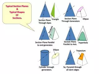
Typical Section Planes & Typical Shapes Of Sections. Section Plane Through Generators. Ellipse. Triangle. Section Plane Through Apex. Parabola. Section Plane Parallel to Axis. Section Plane Parallel to end generator. Hyperbola. Ellipse. Trapezium. Cylinder through

Section Plane Through Apex
E N D
Presentation Transcript
Typical Section Planes & Typical Shapes Of Sections. Section Plane Through Generators Ellipse Triangle Section Plane Through Apex Parabola Section Plane Parallel to Axis. Section Plane Parallel to end generator. Hyperbola Ellipse Trapezium Cylinder through generators. Sq. Pyramid through all slant edges
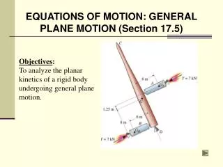
A pentagonal pyramid (side of base = 50 mm and height = 100 mm) is resting on its base on the ground with axis parallel to frontal plane and perpendicular to the top plane. One of the sides of the base is closer and parallel to the frontal plane. A vertical section plane cuts the pyramid at a distance of 15 mm from the axis with section plane making an angle of 50o with FP. Draw the remaining part of the pyramid and the true shape of the cut section d The plane is perpendicular to the top plane, therefore the section line is drawn in the Top View It cuts the base at f and j It cuts the edges at g and h Join these points to o form the section face Section plane 15 r e p c o n m T a b 50o F o’ p1 n1 r1 n’ 100 p’ The true shape of the section is drawn as an auxiliary view to the top view with the reference line parallel to the section plane m1 m’ e’ b’ r’ c’ a’ d’ 50
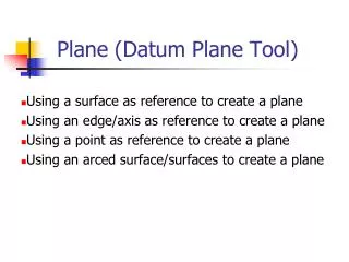
A sphere of 75 mm diameter is cut by a section plane, perpendicular to the FP and inclined at 30oto the HP in such a way that the True Shape of the section is a circle of 50 mm dia. Draw its front view and sectional top view. Draw the FV(circle with dia. 75 mm) and project the TV Draw the cutting plane inFV such that it is 30o to the HP and makes a 50 mm chord on the FV circle Draw concentric circles in the TV(center same as the center of the TV) and project them into the FV Mark the points of intersection of the cutting plane with the concentric circles in the FV and project them into the TV Join these points in the TV to get the sectional TV T 30o F f50 Sphere f75
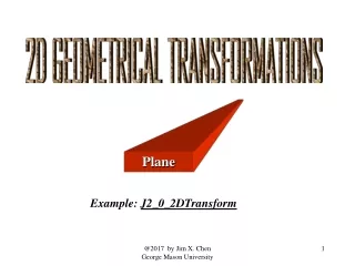
A cube of 65 mm long edges has its vertical faces equally inclined to the FP. It is cut by a section plane, perpendicular to the FP so that the true shape of the section is a regular hexagon. Determine the inclination of the cutting plane with the HP and draw the sectional top view and true shape of the section e PRIMARY AUXILIARY VIEW (True shape of the section plane) d c Angle to be measured d1 45o 45o e1 a1 a b T f F c1 a’, d’ f1 b1 Section plane cuts the Mid points of edges of cube 65 f’, e’ Section plane and reference line are parallel b’, c’
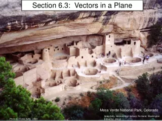
A cylinder, diameter of base 30 mm is standing on its base on ground and positioned in third quadrant. The position of center of upper base is O1(25, 30, 25) and the center of the lower base is O2(25, 30, 75). Points A (0,60,45),B(15, 5, 70) and C(65, 35, 35) lie on a plane that cuts the cylinder in two parts. Draw the two orthographic views of the cut portion of the cylinder. The coordinates of any point (x, y, z) represent distances measured from left profile plane, frontal plane and top plane respectively. Cutting plane is oblique y Generator lines A C 30 • Draw lines across the Top View(generator lines) starting from one corner of the plane upto the opposite side (AB). • Project the intersection points between the generator lines and the side (AB) into the Front View • Join these points with the corresponding corner C in the FV • Project points of intersection of the section and the generator lines from the TV into the FV • Two generator lines should be tangent to the section in the TV to get the width of the section in the FV 20 T 10 B x 10 20 30 10 F O1 20 30 30 C A B O2 z