Download
1 / 50
500 likes | 691 Views
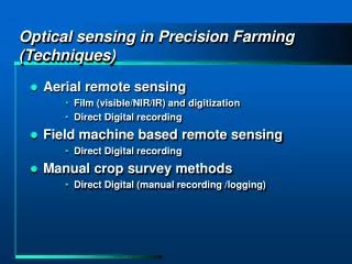
Optical sensing in Precision Farming (Techniques). Aerial remote sensing Film (visible/NIR/IR) and digitization Direct Digital recording Field machine based remote sensing Direct Digital recording Manual crop survey methods Direct Digital (manual recording /logging).

E N D
Optical sensing in Precision Farming (Techniques) • Aerial remote sensing • Film (visible/NIR/IR) and digitization • Direct Digital recording • Field machine based remote sensing • Direct Digital recording • Manual crop survey methods • Direct Digital (manual recording /logging)
Purpose for use of optical sensing in Precision Farming • Used to characterize plant or soil status • Requirement: Calibration of spectral parameters to status • Used to characterize boundaries • Physical • Morphological • Requirement: Accurate spatial calibration (1m actual = 1 pixel) Lat/Lon = f(pixel position)
Issues - What is being measured? • Variability in light source • Filtering of light along path • Measuring units/calibration of sensing system • Geometry • Spatial and temporal frequency of measurements
Typical Multi-Spectral Sensor Construction One Spectral Channel Photo-Diode Amplifier Analog to Digital Converter CPU Filter Illumination Collimator Radiometer Computer Target
Fiber-Optic Spectrometer Optical Glass Fiber Optical Grating Analog to Digital Converter CPU Computer Photo Diode Array
Fundamentals of Light • Light = Energy (radiant energy) • Readily converted to heat • Light shining on a surface heats the surface • Heat = energy • Light = Electro-magnetic phenomena • Has the characteristics of electromagnetic waves (eg. radio waves) • Also behaves like particles (e.g.. photons)
Relationship between frequency and wavelength l Plus Plus Minus Minus
Relationship between frequency and wavelength Wavelength = speed of light divided by frequency (miles between bumps = miles per hour / bumps per hour)
Relationship between frequency and wavelength l + - lKOSU= 3 x 10⁸ / 97.1 x 10⁶ lKOSU= 3 m lred= 6.40 x 10- 7 m = 640 nm Bohr’s Hydrogen = 5 x 10 - 11 m Antenna Plus Plus Minus Minus
Light emission / absorption governed by quantum effects Planck - 1900 Einstein - 1905 One “photon” DE is light energy flux n is an integer (quantum) h is Planck’s constant n is frequency
Changes in energy states of matter are quantitized Bohr - 1913 • Where Ek, Ej are energy states (electron shell states etc.) and frequency, n , is proportional to a change of state • and hence color of light. Bohr explained the emission spectrum of hydrogen. Hydrogen Emission Spectra (partial representation) Wavelength
Photo-Chemistry • Light may be absorbed and participate (drive) a chemical reaction. Example: Photosynthesis in plants • The frequency (wavelength) must be correct to be absorbed by some participant(s) in the reaction • Some structure must be present to allow the reaction to occur • Chlorophyll • Plant physical and chemical structure
Visual reception of color • Receptors in our eyes are tuned to particular photon energies (hn) • Discrimination of color depends on a mix of different receptors • Visual sensitivity is typically from wavelengths of ~350nm (violet) to ~760nm (red) Wavelength
Primary and secondary absorbers in plants • Primary • Chlorophyll-a • Chlorophyll-b • Secondary • Carotenoids • Phycobilins • Anthocyanins
Absorption of Visible Light by Photopigments Sunlight Chlorophyll b Phycocyanin Absorption B-Carotene Chlorophyll a 300 400 500 600 700 800 Wavelength, nm Lehninger, Nelson and Cox
0.5 Visible Near Infrared Reflectance (%) 0.25 Plant Reflectance 0.00 450 500 550 600 650 700 750 800 850 900 950 1000 1050 1100 1150 Wavelength (nm)
Thermal Nature of the Emission of Radiation • Black-body radiation • Matter is made up of inter-related particles which may be considered to vibrate or change energy state • A distribution of energy states exists within a blackbody • Matter emits radiation in proportion to the energy state changes
Wien’s Displacement Law lpeak= 2,897,000 / T where: T = [0K ] l= [ nm] Hot metal example lpeak-sun = 2,897,000/6000 = 475nm lpeak-plant = 2,897,000/300 = 9700nm Point: Emission “color = f(T of emitter)
Planck’s Law Equation: Point: Emission “color = f(T of emitter)
Sun vs. Plant / Soil radiation SUN 6000K Terrestrial 300K
Radiation Energy Balance SUN Earth Temperature of the earth is set by the difference between absorbed and emitted energy If no energy was emitted by the earth, The earth’s temperature would eventually rise to that of the sun
Nature of absorption by the atmosphere Reflected Transmitted Incident Absorbed Radiant energy balance must be computed for each component of the atmosphere and for each wavelength to estimate the radiation incident on the earth's surface Earth's surface Atmosphere
Solar Irradiance NIR UV
Radiation Energy Balance • Incoming radiation interacts with an object • and may follow three exit paths: • Reflection • Absorption • Transmission • a + t + rf = 1.0 • a, t, and rfare the • fractions taking each path Rl0 Rl0 rf Rl0 a Rl0 t
Reflectance • Ratio of incoming to reflected irradiance • Incoming can be measured using a “white” reflectance target • Reflectance is not a function of incoming irradiance level or spectral content, but of target characteristics
Diffuse and Specular Radiation Multiple reflections in the atmosphere cause diffuse radiation
Measurement of Light • Photometry • Measurement of visible radiation in terms of sensitivity of the human eye. • Used in photography and in lighting performance • Photometric measures • Luminous intensity - Candela [cd] • Luminous Flux - Lumen [lm] • Luminance (cd/m2) - [nit] • Illuminance (lm/m2) - [lx]
Measurement of Light • Radiometry • Measurement of the properties of light without regard to human perception • Used for quantifying energy in radiation • Radiometric Measures • Radiant Flux - Watt (W) (rate of energy from source)
Terminology • Radiant flux • Energy in the form of radiation from a source per unit time units passing through a surface = Watt [W] • irradiance • irradiate - to have light radiating on to an object • irradiance - the light emitted from an object surface that is being irradiated
Radiance Energy Flux through a surface per unit of solid angle per unit area of source Watts Solid Angle Steridian [St] per meter square of source
Irradiance Unit Area (m2) Energy Flux through a surface per unit of area Power = Energy / Time [Joules / Second] = [Watts] Power = DE / Time Power = Photons / Time Power = nhn /Time Irradiance = Power / Area = (Photons / Time) / Area Irradiance = [Watts / Square Meter]
Irradiance and Reflectance • Irradiance (Il0) a measure of power per unit area • Reflectance (rf ) is the ratio of reflected to incident Irradiance rf = Il0 rf / Il0
Spectral Irradiance • Power per unit spectral width Area = [ W/m2 ] = Irradiance height = [ W/m2 nm ] = Spectral Irradiance width = [ nm ] = Bandwidth Spectral Irradiance Bandwidth
Computation of Irradiance from Spectral Irradiance • Irradiance for a particular band is the “sum” of Spectral Irradiance across the band times the wavelength
NDVI • Normalized Difference Vegetative Index • Difference increases with greater red absorption • Increase or decrease in total irradiance does not effect NDVI • Typically computed with irradiances, use of reflectance eliminates spectral shift sensitivity
Irradiance Indices Based on ratios of reflected Red and NIR intensity Example Index: Rred / Rnir Spectral shift in illumination prevents use of simple irradiance sensing
Reflectance Indices Based on ratios of Red and NIR Reflectance Red Reflectance: r = Rred / Ired Example Index: rred / rnir Reflectance is primarily a function of target
NDVI • Developed as an irradiance Index for application to remote sensing • Normalized Difference Vegetative Index • Varies from -1 to 1 • Soil NDVI = -0.05 to .05 • Plant NDVI = 0.6 to 0.9 • Typical plants with soil background NDVI=0.3-0.8 • OSU sensors • narrow-bandreflectance based NDVI
Natural Illumination Battery powered Wide dynamic range Low noise 0.75 x 0.25 m field of view OSU Reflectance Sensor
NDVI INIR = 780 ±6 nm IRED =671 ±6 nm
Photo Diode Detector Opto 202 Die Topography Photo Diode Area 2.29mm x 2.29mm 5.2e-6 m2
Calculation of Irradiance from Detector output Responsivity: rl [V/uW] for a particular wavelength, output in volts, V is the product of Responsivity times the Irradience I times sensor area. [ W/m2 ] [V/uW] [m2] For a wide band,
Calculation of Irradiance from Sensor output -cont- Irradiance may be computed from the voltage reading for a narrow spectral band : The average value of Responsivity,rl for the detector must be used
Calculation of Irradiance from Sensor output -cont- Sensor reading, S, is normally an amplified and digitized numeric value Where: V voltage output of the sensor VRange input range of the amplifier-A/D circuit n binary word width of the A/D converter
Calculation of Irradiance from Sensor output -cont Example: Let I = 1 W/m2 A = 5.2e-6 m2 (for the Burr-Brown 201) rl= 0.5 V/mW (for l = red) VRange = 5 V n = 12 bits