Download

1 / 13
130 likes | 325 Views
PIKA Technologies Inc. Digital Logger Application Sample March 2010. What is it?. Sample Application developed in C++ Can be used to passively record calls from Digital T1/E1 spans Works on HMP 2.7+ platforms (Windows, Linux) with PIKA Digital PCIe Boards

E N D
PIKA Technologies Inc.Digital Logger Application Sample March 2010
What is it? Sample Application developed in C++ Can be used to passively record calls from Digital T1/E1 spans Works on HMP 2.7+ platforms (Windows, Linux) with PIKA Digital PCIe Boards For Windows, a wav converter application is included to convert from raw to Wav format
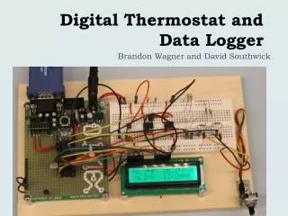
Overall Architecture Description At start-up the main thread will create all the required instances. It will therefore create the digital board instance and its associated members. Each instance will communicate with the PIKA Driver (PKH_XXX) to configure and start it’s associated objects. The main thread will then spawn the event thread. The event thread is used to handle asynchronous events from the PIKA driver. For debugging purposes an event message logger (not to be confused with the digital logger) has been included to show events on the console and can also be injected to the PIKA Driver logs. The DigitalBoard instance contains 4 span instances and up to 2*30 calls. A particular call is associated to 1 channel for each of 2 spans. We should note that signalling channels are created but are not actually started. Each Span instance contains 1 hdlc and up to 30 channels.
Getting Started • Install the PIKA Low Level HMP API on a PC ( 2.7.x or newer ) as described in the Getting Started Guide • Remove the line jumpers on the PIKA HMP PCIe digital board. • Install the board in the PC • Cabling - requires some specific wiring • Download, Compile, and run the Digital Logger application
Sample Code - Overall Architecture • At start-up, the sample application will statically create all of the resources needed to Passively Record on all channels and spans • The event thread handles asynchronous events from the PIKA driver. • For debugging purposes an event message logger (not to be confused with the digital logger) has been included to show events on the console and can also be injected to the PIKA Driver logs. There are multiple debug levels that can be controlled via a compile flag. • A 4 span board can log 2 T1 or E1 connections • Each Span uses an HDLC to capture ISDN messages and via the PIKA Low Level API, these messages get sent to the application for processing.
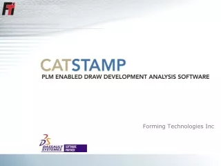
Overall Architecture Description • The Hdlc instance is used to handle incoming ISDN Q.921/Q.931 messages. When a valid Q.931 message is decoded (cisdntranscoder.cpp), the channel detected shall setup a call. • The call will then start listening to the conference between the 2 previously associated channels and output the conversation to a file. The filename will have the following format: • Board_#_Call_#_$date$.wav • When a ISDN Disconnect or Release message is detected, the audio file will be saved and closed.
Application thread Diagram PKH_BOARD_XXX PIKA Driver Main Thread PKH_SPAN_XXX PKH_CHANNEL_XXX Spawn Thread Event Thread Incoming Event
Class Hierarchy and containment Logger (singleton) LogClient BaseEntity System 1 DigitalBoard n 1 4 Span 1 Hdlc 1 Channel 32 Call 2*32
Passive Logging Passive Logging – Application Call Logs Process ISDN Messages PKH_SPAN_HDLC_X Audio Record AudioFiles CO RX TX RX- Tip/Ring 0 HDLC Jumpers MediaProcessing T1/E1 Span 1 HDLC RX- Tip/Ring 2 HDLC 3 HDLC HMP Digital Board - PCIe PBX TX RX
Passive Logging Architecture PBX CO TX RX RX TX Tip / Ring Tip / Ring RX RX HDLC Audio Audio HDLC M M ISDN Events ISDN Events Conf M Record File
Passive Logging – Cabling Telco PBX RX Tip TX Tip RX Ring TX Ring RX Tip TX Tip RX Ring TX Ring Do No Connection Do No Connection RX TIP RX RING TX TIP TX RING RX TIP RX RING TX TIP TX RING Span 0 Span 1 PIKA Digital T1/E1 HMP Board - PCIe
Call/Span/Channel allocation Span 1 0 1 2 3 28 29 30 31 Span 2 0 1 2 3 28 29 30 31 0 1 3 2 31 28 29 30 Call Ids 32 33 35 34 63 60 61 62 Span 3 0 1 2 3 28 29 30 31 Span 4 0 1 2 3 28 29 30 31
Where can I find it? • The Source code is located under: • http://svn.pikatech.com/customercare/trunk/samples/DigitalLogger/ • Some additional info: • http://forum.pikatechnologies.com/showthread.php?t=170