Download
1 / 1
20 likes | 228 Views
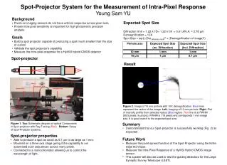
Spot-projector. Diffuser. Extension Tube. Neutral filter. Infinitube lens. CCD. Light guide. Micro-objective lens. Figure 1 . Top : Schematic diagram of optical Components in Spot-projector with Ray Tracing ( Red ). Bottom : Setup of Spot-Projector systems. Pinhole. Result.

E N D
Spot-projector Diffuser Extension Tube Neutral filter Infinitube lens CCD Light guide Micro-objective lens Figure 1. Top: Schematic diagram of optical Components in Spot-projector with Ray Tracing (Red). Bottom: Setup of Spot-Projector systems. Pinhole Result Linear Stages Expected Spot Size Diffraction limit = 1.22 λ f/D= 1.22 λ f/# = 0.61 λ/N.A. = 2.78 μm Demagnification = 10X Spot Size = sqrt( (Dia.diffraction limit)2 + (Demagnification of Image)2) Pinhole size Expected Spot Size (no. Diffraction) Expected Spot Size (Incl. Diffraction) Figure 2. Image of 10 mm pinhole with 10X demagnification. Blue lines represent the radius of the image. Left: Imaging of 10 mm pinhole. Right: Plot of intensity profile from selected radius (Blue region). Red line is at FWHM (59.5 pixels, 9 μm/pix). FWHM is 119 pixels and corresponds 1 mm image size. It is good match to the expected spot size. 10 mm 1 mm 1 mm 10 μm 1 μm 5.7 μm Spot-Projector System for the Measurement of Intra-Pixel Response Young Sam YU • Background • Pixels on imaging sensors do not have uniform response across pixel area • Known intra-pixel sensitivity is important for high photometric precision analysis • Goals • Build a spot projector capable of producing a spot much smaller than the size of a pixel • Validate the spot projector’s capability • Measure the intra-pixel response for a HyViSI hybrid CMOS detector • Summary • Demonstrated that our Spot-projector is successfully working (Fig. 2) as expected . • Future Work • Measure the point spread function of the Spot-Projector using the Knife-edge technique. • Measure the Intra-Pixel Response of a HyViSI Hybrid CMOS image sensor. • This system will also be used to test the guiding detectors for the Large Synoptic Survey Telescope (LSST). • Spot-projector properties • Able to produce a spot as small as 5.7 µm to as large as 1 mm. • Mounted on a three axis stage giving it the capability to run automated scan sequences across many pixels. • Connected to a monochromator allowing us to control the wavelength of light.