Download
1 / 23
230 likes | 460 Views
NCSX Coil Services. P.L. Goranson Work Package 161. Coil Services System Description. The coil services consist of the cryogenic feeds inside the cryostat, serving all of the coils, including conventional. It includes the specification of requirements for the coil protection system.

E N D
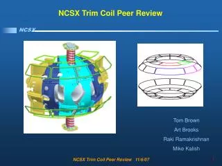
NCSX Coil Services P.L. Goranson Work Package 161 SC Project Review of NCSX, April 8-10, 2008
Coil Services System Description The coil services consist of the cryogenic feeds inside the cryostat, serving all of the coils, including conventional. It includes the specification of requirements for the coil protection system. Lower-level elements include: LN2 Distribution System (WBS 161); SC Project Review of NCSX, April 8-10, 2008
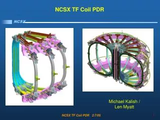
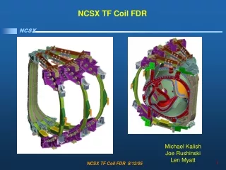
NCSX Coils SC Project Review of NCSX, April 8-10, 2008
WBS 161LN2 Distribution System Description This element covers the distribution of liquid nitrogen (LN2) coolant within the cryostat. The system serves all the actively cooled coils: TF (WBS 131) PF (WBS 132) Modular (WBS 14) Scope Work includes engineering design, procurement, and fabrication of manifolds, cooling hoses, jumper hosing, valving, and associated supports. Work in this WBS ends with delivery of components to machine assembly operations. Interfaces I&C is procured in 1408. WBS161 includes routing and distribution of coolant between coil input/output terminations and the supply/return manifolds. WBS17 provides supply/return headers and hook up interfaces in the Cryostat. Valves are included in WBS161. SC Project Review of NCSX, April 8-10, 2008
Central Solenoid, TF, and PF Configurations PF1a coils from NSTX are baseline Upgrade Configuration • Baseline is PF1a, PF4, PF5, and PF6 (2 each, upper and lower). • Device can be upgraded if desired, where PF1a is replaced by PF1, PF2, PF3. Baseline Configuration SC Project Review of NCSX, April 8-10, 2008
Modular Coil and Conventional Coil Cooling • Requirements • Operate at 77 K with LN2. • Operating pressure minimum 5 atmospheres absolute. • Electric breaks in MC coil coolant lines poloidally. • Electrical current limitation between cooling components. (bypass resistors • isolate hoses to ground) • - TF and PF hoses electrically isolated at coil terminations as • well as headers • Provide flow balance between systems. SC Project Review of NCSX, April 8-10, 2008
M MC hook up 1-48 Spares PF pair Return Header 1-14 M 2 1 4 2 1 2 14 3 5 6 7 45 46 47 48 1 PF Coil pair TF Coils 1-6 Resistor Costs reflect design in Cooling System Diagram shown below G-10 Insulator 6 1 2 3 4 5 2 Return Header Inner Outer PF (4, 5, 6) TF MC PF1 Insulated jumper Poloidal break One side of a Modular Coil shown Supply Header 2 1 5 6 1 2 3 4 TF Coils 1-6 PF Coil pair 4, 45 2 14 1 5 6 7 46 47 48 1 2 1 2 3 4 5, or 6 Field Period Supply Header Spares MC hook up 1-48 PF Coil pair 1-14 1, 2, or3 Cryostat Boundary plg 3/20/08 • Dual supply and return manifolds • Individual controls are not required, a single valve in MC return balances • both manifolds • Valve and monitoring is outside cryostat where it is accessible • Individual circuits are passively (self) balanced Flowbalance Flow volume SC Project Review of NCSX, April 8-10, 2008
Length of Length of Minimum Pressure ID tracing hose flow required Actual flow drop (in) (ft) (ft) (gpm) (gpm) (atmos) MC 2.42 0.18 4 18 1.1 1.2 PF1 2.42 0.354 304 24 1.1 1.1 PF2 2.42 0.354 304 24 1.1 1.1 PF3 2.42 0.354 304 24 1.1 1.1 PF1A 2.42 0.354 178 24 1.1 1.2 spares 2.42 0.5 0.5 PF4 4.51 0.354 861 21 1.1 1.4 PF5 4.51 0.354 1100 21 1.1 1.2 PF6 4.51 0.354 786 18 1.1 1.4 TF 4.51 0.312 355 18 1.6 1.6 Flow distribution PF1A is used in CD4, replace by PF1, PF2, and PF3 in future operation. Pressure drops fall in two well defined groups. SC Project Review of NCSX, April 8-10, 2008 P. L. Goranson - page 8
Typical manifold • Manifolds lie outside TF coils • supply near bottom of VV • return near top of VV G11 coupling manifold resistor SC Project Review of NCSX, April 8-10, 2008
Manifold Jumpers Transition to flex hosing at the winding form SC Project Review of NCSX, April 8-10, 2008
Manifold hose insulators • Hoses are isolated from the • manifolds by G10 plugs • - prototype will be tested • at 77K • orientation of individual • connections is TBD G10 CR Male / Female coupling 316 SS braided hose with 5/16 OD straight tube coupling at both ends Resistor 316 SS Yor-Lok 5/16 OD tube one end and ¼” NPT on other end SC Project Review of NCSX, April 8-10, 2008
LN2 hoses are catalog items. Lengths are based on ProE models. Manifold designs and prices are based on a similar design used on the VV. Sizing is based on thermo hydraulics performed by Engineering. Material cost is estimated on a $ per lb at current market. Supports are based on a $/length of hose. Engineering time is based on number and type of drawings for each element, specifications, and the analyses anticipated. Cost Estimate Basis SC Project Review of NCSX, April 8-10, 2008 P. L. Goranson - page 12
LN2 Distribution System (WBS 161) Design is straight forward and procured items are by and large commercially stocked. Manifolding is similar to gas system on VV, which is complete and costs are well documented. Maturity – medium Routing and interfaces arein early design phase and design is pre- PDR. R&D required. Complexity – low Cost Estimate Risks SC Project Review of NCSX, April 8-10, 2008 P. L. Goranson - page 13
RiskMitigation Schedule Milestones An extra full time designer was assigned to Coil Services to assure schedule is met. Hoses will be 100% leak checked at delivery to prevent delays after installation. (lesson learned from VV) Design Integrity R&D at MDL will confirm functionality of G10 insulators and flow rate in corrugated hoses. SC Project Review of NCSX, April 8-10, 2008 P. L. Goranson - page 14
WBS 162 Coil Electrical Leads Description This element covers the electrical leads within the cryostat, serving all the coils: the TF, PF, External Trim (WBS 133), and Modular Coils. Scope Work includes engineering design, procurement, and fabrication of cables, mounting brackets, thermal transition boxes, and associated supports. Work in this WBS ends with delivery of components to machine assembly operations. Interfaces The WBS161 interface begins at coil terminations and ends at the cryostat thermal transition/terminal box. It does not include I&C, bus work, or routing in the test area. Requires penetration of cryostat. Share real estate used by core structural support, floor mounted utilities, bus supplies, diagnostics, etc. SC Project Review of NCSX, April 8-10, 2008
Connect between bus supply in test cell and coil terminals inside cryostat. Operate nominally at 77-80 K but no active cooling is required, Cryo environment is sufficient to return temperature to operating level between shots. Provide Cryostat seal interface. Minimize icing Maintain positive pressure in Cryostat React internal magnetic loads. Cancel (minimize) field errors. Lead Requirements SC Project Review of NCSX, April 8-10, 2008 P. L. Goranson - page 16
Status • MC design is most mature. • To date, most of design effort has concentrated in this area as it is the more challenging. • Conventional coils will be handled in a similar manner and use similar components.( cable, brackets, terminations, spacers, etc.) SC Project Review of NCSX, April 8-10, 2008 P. L. Goranson - page 17
MC Lead Configuration 1” long spider/loom 5/16” Stud Standard 1.5” Pipe Clamp (1/8” thk x 1” Wide) Casting Cable is 250 MCM SC Project Review of NCSX, April 8-10, 2008 P. L. Goranson - page 18
SystemLayout SC Project Review of NCSX, April 8-10, 2008 P. L. Goranson - page 19
Service routing to test cell penetrations PF leads TF & TC leads MC leads SC Project Review of NCSX, April 8-10, 2008 P. L. Goranson - page 20
MC Lead Stub Connections MC B lead stub MC A lead stub SC Project Review of NCSX, April 8-10, 2008 P. L. Goranson - page 21
Lead Routing Services will be routed to each of the three C-C interfaces. SC Project Review of NCSX, April 8-10, 2008 P. L. Goranson - page 22
Modular coil Interface at Cryostat Leads transition thru the cryostat, to room temp. Cryostat Floor Leads Junction Box (Clear cover removed) Top View of an 8” diameter pipe chase showing the (6) modular coil leads cables from a field period Pipe Chase Hard Bus to power supplies SC Project Review of NCSX, April 8-10, 2008 P. L. Goranson - page 23