Download
1 / 29
290 likes | 519 Views
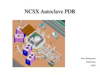
NCSX Autoclave PDR. Steve Raftopoulos Frank Jones 1/8/03. Scope. This review covers the mechanical and electrical design of an autoclave chamber that will be used for the epoxy impregnation/curing of the NCSX Modular coils. Agenda. Intro & Background Requirements Design/Drawings

E N D
NCSX Autoclave PDR Steve Raftopoulos Frank Jones 1/8/03
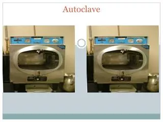
Scope • This review covers the mechanical and electrical design of an autoclave chamber that will be used for the epoxy impregnation/curing of the NCSX Modular coils.
Agenda • Intro & Background • Requirements • Design/Drawings • Analysis (preliminary calculations) • Test requirements & Plans • Review of Peer Review Chits • Manufacturability • Electrical Presentation (F. Jones) • Cost/Schedule
Background The shape of the NCSX modular coil makes it impractical to build a rigid metal case, therefore a fiberglass case will be hand formed around the twisting geometry. For epoxy impregnation, typically a sealed case is built around the coil. Vacuum is pulled on the case, enabling the epoxy to flow into the winding and very effectively fill voids. Coil X-section
Background (cont.) Since this case is substantially weaker than a metal case, a vacuum will be pulled on both sides, minimizing the stress from differential pressure.
Major Design Requirements • Large enough to accommodate the NCSX modular coil sections. • Can achieve and maintain a base vacuum of 1 torr in ~ four hours. • Can heat coil sections to 130 degrees centigrade. • Can accommodate a positive pressure of 15 psig. • Provide ports for: • Epoxy feedthroughs • Thermocouple feedthroughs • Viewports • Man entry
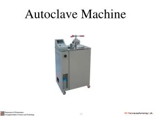
Design • Dimensions - 5/8” thick, 14’ dia x 11” tall tube. • ASME dome heads (std catalog item). • 304SS vacuum chamber. • Support stand
Design (cont.) LOWER DOME PLATFORM & VESSEL SUPPORT STRUCTURE • Floor at bottom of tank capable of supporting the modular coil (8 k#). • Platforms, external and internal to facilitate epoxy tanks, personnel ingress/egress, access to attachment of thermocouples and epoxy sprus. • 60-70 kilowatt resistive heating • Circulating air as heating fluid
Design (cont.) • Circulating, heated air will provide the heating. • Resistive heating elements, bolted to tank surface and in the air-stream will heat the air and maintain temps during vacuum operation • Thermocouple readings shall provide feedback control of the heater power and/or airflow.
Design (cont.) • Ports: • Two, 16.5-inch diameter ports for epoxy feedthroughs, each containing 19 sprus, will be available. One port just above midplane and one port at top of cylinder. • One, 16.5-inch diameter port that contains multiple, smaller (2.75”) thermocouple feedthroughs. • Two, eight inch ports for the circulating heated air. Inlet port located in the lower dome, while the return port is located at the top of the cylinder. • One 10-inch diameter port that contains electrical feedthrough(s) for internal lighting.
Design (cont.) • Ports • One 32-inch man-way, with T-bolt, hinged closure. • Ports • Four racetrack-shaped or six 8-inch dia. round viewports for inspection, located to provide full viewing coverage of the spru attachment points to coil.
Design (cont.) • Heating system • Heating system consists of 36, 2kwatt electric resistive heaters, mounted to the outside surface of the tank. • Additionally, 10 kwatt of resistive heating shall be available within the air circulating piping to provide heated air for vent up from vacuum at 50 degree centigrade. • Elements can be turned on in banks, allowing variable heating rates tailored to accommodate the modes of operation. • Circulating air will improve heat transfer (convection oven effect) • Air is introduced at lower dome and is diffused by the perforated floor.
Operating modes • In Air @ STP, heat entire mass from room temp. to 45 Deg C. • Pull vacuum, maintain 45 C and impregnate coil. • Vent with air to STP and raise temperature (slowly) from 45 to 110 C. • Hold at 110 C for 5 hours • Raise temperature to 125 C and hold for 16 hours • Turn off heating system and allow to cool naturally.
Manufacturing Requirements • 304 SS chamber. • Magnetic permeability not important. • O-ring seals. • Man-entry door for access when lid is in place. • Internal lighting. • Viewports for inspection during impregnation phase.
Operational Requirements • Achieve vacuum <1 torr in 4 hours. • Room temp to 45 C in 4 hours. • 45 C to 110 C in 15 hours. • Temperature monitoring and feedback control of heating.
Analysis(preliminary calculations) • Calculations have been performed for the following: • Mechanical loads • Hoop stresses are very low. • Have FS of ~5 for buckling critical pressure. • Thermal • Tank and components will require ~ 50 kW to heat in desired time frame. This considers heat loss from convection and conduction (very minor). 1.5 inch of thermal insulation will be installed onto tank. • Vacuum • One 50cfm pump should be able to pump down the chamber to ~1 torr in 4-5 hours. Recommend that we have 2 pumps available. • These calculations will be formally checked and approved prior the FDR.
Peer Review Chits • Avoid overly complicated weld details. • Working with shop in developing details • Save cost by welding legs directly to the tank. • Detail changed • Consider using less expensive ANSI flanges for feedthrough connections. • Will review on case by case basis, need some vacuum flanges. • Protect pumps from VPI Process • Effluents will be cryo-trapped before getting to pump. • Remove ring girder for floor. • Removed. • Keep man access door away from facing south. NB Boxes (tritium source) • Will orient door away from NB boxes. • Consider vendor fabrication of tank, including flanges. • This is the default plan. • Consider removing the circulating system and have an internal fan. • Need a heated section of pipe for warm air introduction.
ES&H concerns • The project is committed to the use of engineering and administrative controls to eliminate and/or minimize hazards to workers and the environments • Environmental • We’ll be pumping the off-gassing from the epoxy (Hysol or equivalent) through the vacuum pumps and into the test cell. We will cold –trap these vapors. • Safety/IH • The autoclave chamber will be a confined space. Hazards include: • Oxygen deficiency • Electrical • Hot surfaces • Lifting/rigging • Elevated workspace • Vacuum hazards • These are hazards that have been successfully dealt with
Manufacturability (buy vs. build) • We plan to have the tank fabricated at outside vendor. The ports/flanges will be fabricated at PPPL. • We will furnish procurement with a set of approved drawings for the basic tank within the next 2 weeks. • We plan to purchase (or locate on-site) all other components that integrate into the system. • We see no major procurement issues at this time. All components are standard catalog items. Even tank domes are std. ASME design.
Testing Requirements & Plans • Manufacturing: • Weld inspections • Conformity to print • Operational: • Vacuum leak check • Heating system check • Vacuum pump check • PTP: • Perform dry run (to operating temperature) with empty chamber • Impregnation tests: • Impregnate the curved T-section test castings • Impregnate the prototype modular coil
Primary Goals (Electrical) • Develop a portable low cost power system. • Provide adequate 480v power for heater and vacuum pumps. • Provide 208/120v power for secondary systems, control systems and general use. • Develop a flexible control system. • Incorporate personnel safety into operations.
Heater Layout Mount all heaters in pairs on exterior of tank in 3 rings. The top and bottom rings are primary heaters consisting of 24-2000w strips. The center ring has 12- 2000w strips for secondary heat.
Electrical Power/Controls/Instrumentation • Power Requirements • Heating Elements (Approx. 75 KW total) • Lighting • Heated Air and Circulation Fan • Vacuum Systems All of the above can easily be supplied from two 480v, 3 phase feeders readily available in the Test Cell (1- 200A receipt. And 1- 100A receipt.) • Control Contactors will be used for on/off control of Heaters, Fan and Vacuum pumps in order to allow the possibility of future upgrade to automatic control (PC or PC/PLC based). Initial design will employ Thermocouple Controllers (with manual override) to maintain oven temperature. • Safety -All heaters and vacuum pumps can be locked out/isolated when personnel access the autoclave. -Autoclave shell temperature will be monitored.
Electrical Power/Controls/Instrumentation • Instrumentation • Internal and external thermocouples will be wired to a Patch Panel so as to provide flexibility in choice of which thermocouples to monitor and which to use as control thermocouples during oven operation. • Vacuum/Pressure will be monitored • Wiring/Layout _All internal connections to autoclave internals will be made through electrical vacuum feedthroughs _External wiring and equipment layout will be designed such that the autoclave may be relocated in the future with minimal re-wiring.
Costs • Major M&S expenditures • Vacuum chamber $30,000 • Viewports $2000 • Man-way $1500 • TC feedthroughs free • Pumps free • Piping $2,000 • Valves $2,000 • Insulation $3,000 • Epoxy feedthrough ports free • Heating elements $6,000 • Structural steel $5,000 • Electrical M&S $15,000
Costs • Shop Labor estimates (mechanical & electrical) • Vacuum chamber machining 20 man-days SM • Ports (fab/weld/install) 20 man-days SM • Chamber legs/floor 15 man-days SM • Install heating elements 15 man-days TB • Chamber setup in TC 10 man-days TB • Vacuum piping fab 10 man-days SM • Vacuum system setup 10 man-days TB • Chamber setup in TC 10 man-days TB • Insulation 5 man-days TB • Platforms 10 man-days TB • Misc. Shop 15 man-days TB • Electrical Shop 40 man-days TB • Electrical Field 26 man-days TB • Totals • 65 M-days SM, 56 M-days in budget • 141 M-days TB, 100 M-days in budget
Schedule • Drafting/design Nov. 25 • Peer Review 12/9/02 • PDR 1/8/03, today • RFQ Tank & lids Jan • Place tank/lids order early Feb • Fab stand and ports Feb-March • Receive Tank/Lids April 1 • Mod Tank/Lids April/May • Ready for leak check June 1 • Transfer to Test Cell June 5 • Connect to services July 1 • Shakedown/PTP July • Ready to go August 1
TBD by FDR • Review/approve specification • FMEA • Complete detail drawings • Check/approve calculations