Download
1 / 27
280 likes | 420 Views
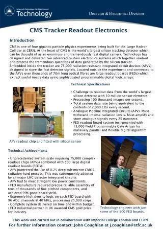
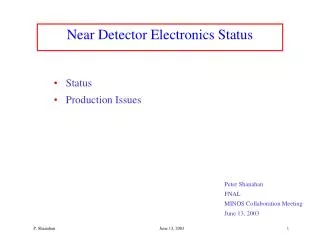
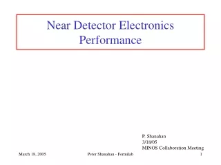
ECAL OFF-DETECTOR ELECTRONICS Jean-Louis Faure Saclay OD “collaboration”: Cern / LIP / LLR / Saclay. Barrel Super-module Readout Unit. 12 VME64x crates. D C C. T C C. C C S. 6 VME64x crates. End-cap 40 ° Readout Unit. D C C. T C C. T C C. T C C. T C

E N D
ECAL OFF-DETECTOR ELECTRONICS Jean-Louis Faure Saclay OD “collaboration”: Cern / LIP / LLR / Saclay
Barrel Super-module Readout Unit 12 VME64x crates D C C T C C C C S 6 VME64x crates End-cap 40° Readout Unit D C C T C C T C C T C C T C C C C S Timing, Control & L1A Trigger primitives Xtal Data TRIGGER D C C C C S T C C VME Controller DCC (Data Concentrator Card) … … DAQ CCS (Clock & Control System) TCC (Trigger Concentrator Card) 5 x 5 Entities Trigger Tower (Barrel) SuperCrystal (EndCap) Num of PbW04 crystals: 61200 Barrel 14648 End-cap 68 TT per SuperModule (x 36) 34 to 36 SC per 40° (x 18) ON-DETECTOR 800 Mbits/s OFF-DETECTOR SRP 1.6 Gbits/s 1.2 Gbits/s (SLB) S-Link Max Data Rate 2 kByte * 100 kHz L1A (100 kHz)
EE- Topology Per End-Cap DCC-48i (Equal Data Rate) TCC-48i Optimization of inputs usage http://polywww.in2p3.fr/%7Ebusson/cms/ECALElectronics/OffDetector/TCC_ENDCAP_Web/InputsTCCe.html
TCS TTC T C C L1A FE Configuration @100 kHz Trigger primitives @40 MHz Regional Calo TRG Regional Calo TRG Global TRG Global TRG SRP TTS signals SR flags SLB Xtal Data @100 kHz DAQ DAQ TTC TTS OD C C S TT bits D C C
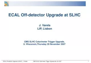
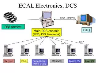
Control& Clock System (also used in Tracker / Preshower) C C S CERN • Clock / Trigger Distribution in side a Sub-System • Toward On-Detector • Inside the subsytem DCC / TCCs • Strong “link” to the ON-Detector via the token ring and the Clock requirements • Control • Slow Control (download On-detector configuration) • Manage the Different Triggers Configurations • Physics events • Laser • Pedestals • MEM test pulse • MGPA test pulse • TTS (back pressure) merging
mFEC mFEC mFEC mFEC mFEC mFEC mFEC mFEC CERN FEC-CCS Block Diagram VMEinterfaceFPGA Local Bus VMEbus • Support for 1~8 control rings per board. • VME 9U board. • VME64x compatible. • Control information passes through the VME bus. • Fast Timing Signals passes through the TTC link. Fast Timing signals JTAG TriggerFPGA QPLL TTCrx TTC link ECAL TTC/TTS bus
Piggy Back Board 4 NIM to TTLTTL to NIM translators IN 4 OUT CCS Clock TTC Encoder L1 B<7:0> Clk40 Clk160 TTC signalto DCC/TCCs Trigger FPGA design. CERN CCSLocal Bus Trigger FPGA Trigger CommandManager Local Businterface&Control Registers Clk40_L1to mFECs Clk40_L1 TTCrx L1ACCEPT L1 Control Ring Clock Encoder BRCST<7:2> 110 101 111 TTCRX_RDY Clk40 Clk80 QPLL 40MHz TTC in 80MHz 160MHz Clk40
CERN CCS V3a (ECAL compatible) In production • PCBs were sent for assembly mid feb 06 (130 PCBs) • Expect to have boards back by mid April. 2006 • Production testing will be done at CERN. • Estimated production testing duration: 2 weeks
T C C 3. Classifies the Trigger Towers in 3 categories depending on the total ET: SLB and transmits this classification to the SRP @L1A rate. Trigger Concentrator Card TCC functions: 1. Opto-electronic conversion and deserialization of the input Trigger Primitives that arrive @40 MHz from the FE electronics. Encoded the TPG 2. Completes the Trigger Primitives calculation for the End-Caps performing the geometrical mapping between the Trigger Towers () and super-crystals (xy). ET < LT, LT < ET < HT, ET > HT 4. Stores the Trigger Primitives during the L1A latency for subsequent reading by the DCC upon reception of the L1A.
From TCC-Tester Counters emitted by the TTC-Tester in 72 inputs patterns received analysed by L.A. All channels ok
Fan-out board TTCvi/ex SLBs TCC68v1 TCC68v0 TCC-Tester
TCC Production Plan • Full TCC68 production: 40 boards (36 + 4 spares) • The tender has been sent on october 26th • Candidate chosen on feb 1st : ALTREL (manufacturer of the 4 TCC68v1) Unit cost: • 5100 euros (ALTREL) • Components provided by us for the production: 1500 euros (deserializers etc.) • total ≈ 6600 euros / boards • Beginning of the production: march 10th, meeting with ALTREL • definition of the JTAG tests, Takaya (flying probe) etc • Agreement on the schedule • delivery of all the components provided by us: chips, front-face, etc… • 3 boards for qualification from the company ≈ 9 May 2006 • Integration of the first Off-Detector crate in end of May/june 2006 • End of production ≈ mid-august 2006 • End of OD integration ≈ december 2006 ? • On going task: development of lab JTAG test for debugging/maintenance
T C C SLB TCC Constraints: 1.Synchronus traffic on Input (NGK) Output (SLB) 2. Minimum delay to perform the tasks (time budget) • Consequences: • Use the CIMT protocol on Input (2.5 Clk) • High density Implementation • High Power consumption
T C C SLB Synchronization & Link Board (also used inHCAL) LIP SLB functions: 1. Plays the role of the interface between the OD and the Regional Calorimeter Trigger. 2. Performs the synchronization of the trigger data that arrives @40 MHz (with the granularity of a Trigger Tower) using synchronization circuits. Synchronization circuits build online histograms to survey the LHC bunch crossing structure. Each Trigger Tower time structure is aligned w.r.t. the BC0. 3. Performs the serial transmission of the synchronized trigger data to the Regional Calorimeter Trigger @1.2 Gbits/s.
LIP • SLB FULL Production Accomplished !! • 1210 Boards • HCAL Production (DONE) • ECAL Production (DONE) • All Cables components arrived • Procurement for cable production • SLB SYNC RX_CLK errors Identified! • Wrong SLBs Terminations (all being replaced ) • Data Alignment • TCC data was misaligned relatively to Tx CLK • SLB Accumulators seems to be the best way to easily check data stability, but is not showing all data misalignments! • Modify the SLB input Design to latch input data … • -Makes minimum SLB latency 3 clocks, maybe 2 clocks possible! • TCC data misalignment correct with new firmware * • HCAL data seems all aligned * • * memory contents, not real data
D C C LIP Data Concentrator Card • Asynchronous Output (@ L1A rate) • Xtal Data • = (25 Xtals/TT * 10 samples/Xtal * 2 byte/sample) + 60 control byte • =560 byte/channel • DCC Data • = 560 byte/channel * 68 channels = 40 kbyte • Asynchronous Output • Limited by DAQ to 2 kbyte SRP & ZeroSup • DDC Tasks • Input Handler (using 8b/10b protocol) ‘we have time’ • Buffer Handling • Data format
LIP DCC
BOE, Trigger Type, LA1, BCID ZS, SR, DCC errors Enabled channels BCID,EVID,TCC ID, TPG#1 TPG#2 … #5 Coarse Grain Data (TCC) (Trigger Primitives) TPG#66 … #68 BCID,EVID,SRP ID, SRF#1...#4 SR flags (SRP) SRF#53 … #68 BCID,EVID,TT/SC ID StripID,CH ID, ADC#1…#3 ADC#4 … #7 ADC#8 … #10 Fine Grain Data (DCC) (Xtal data) StripID,CH ID, ADC#1…#3 ADC#4 … #7 ADC#8 … #10 Data format
SRP Saclay SELECTIVE READOUT PROCESSOR • Working at L1A rate • Input TT bits from TCCs • Performing Sliding window method on the whole ECAL (across boundaries) • Output SRP Flags to DCCs • Time budget 3-4 ms High Speed Traffic All Across the ECAL: i.e. TCC / DCC / AB
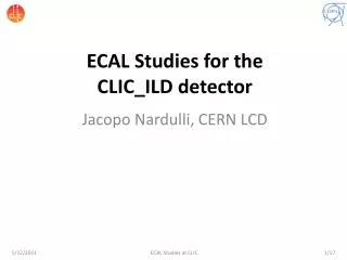
AB Rx Up to 12deserializers SNAP12 DCC SFP Tx Up to 12serializers Deserializer Rx Saclay Reminder: Optical components TCC-AB and AB-DCC links Distribution modules Individual LC fibers 12-fiber MTP cables TCC SFP Serializer Tx
SNAP12 SNAP12 AB2 AB3 Rx Tx Up to 12deserializers Up to 12Serializers AB-AB links Saclay Passive optical cross-connect • Components acquired for TCC-AB and AB-DCC links • 200 sets of SFP Transceivers – Cages – PCB connectors • 162 is needed • 200 individual LC-LC fiber optic cables (20 more to come) • 162 is needed • 40 12-fiber MTP cables • 24 is needed • 30 Distribution modules • 24 is needed • 10 Rack mount 1U panels • 8 is needed • Shielding of individual LC-LC fibers to be ordered • Same flexible shields as for monitoring fibers • 216 fibers (162 + 54 spares): (108 + 36) TCCs + (54+18) DCCs
ABTx ABRx DCCTx Saclay Algorithm BoardHardware P1 J0 P2 VME buffers Power supply Xilinx V2Proxc2vp70-6-ff1704 BS controller &JTAG chain Same hardware for AB and AB Tester Core FPGA VMESerial linksAlgorithms FPROMs Memory Clocksynthesizer TCS interface SNAP12 MSA pluggableparallel optic modules QPLL TTCrx TTCRx RJ45 connectors Aux. connector TrueLite TTSIN TTSOUT Cons., JTAGEthernet TTSIN O/E
Saclay • Schematic • done • Prototype production • Routing: March-April 2006 • Cabling: May-June 2006 • Tests: July-August – Saclay, September – LLR/CERN • Production • October-November • Barrel AB tests: December 2006 – February 2007 • Installation, Commissioning • March-April 2007 • End-cap AB Tests • May-June 2007 SRP • AB hardware • Firmware • Cadenced at 80 Mhz • Occupies 46% of logic cells in 2VP70 device • Simulated latency From L1 Accept till SRF at DCCs < of 3 µs • Philippe GRAS will start working on online software in December 2005 • AB configuration and slow control • AB test bench software • The online software based on XDAQ • Development will be started with software-emulated cards • The foreseen schedule is: • Configuration software: December 2005 – March 2006 • Configuration database: April 2006 • Run control and test bench software: May – June 2006 • AB prototype testing: July – September 2006 • Integration with the CMS run control software: October – November 2006 Software
EE EB EB Saclay Shielding of LC-LC fibers 1m shield with 9.9 mminternal diameter4 x 2mm fibres (1 spare) 0.75m of unshielded fiber SRP 17.5m shield with 23.2 mminternal diameter36 x 2mm fibres (9 spares) 0.75m of unshielded fiber 12 TCC3 DCC 5 spares 30 distribution modules in 10 1U rack mount panels (6 cassettes in last 2 panels arespares) To be added to EMDB 3 TCC3 DCC 2 spares TTC 1 m shield with 9.9 mminternal diameter8 x 2mm fibres (2 spares) 0.75m of unshielded fiber 3 TCC3 DCC 2 spares TEST 6x17.5m = 105m of 23.2mm shield 6x5x1m = 30m of 9.9mm shield
ODs on production CCS / DCC / TCC68 Prototypes Tests / Debugging / Qualification Production Test Benches AB will come late Hardware reminder DCC Tester LIP foreseen in fall TCC Tester LIP foreseen in fall Are needed to test the full functionalities (frequency,…..) AB-Setup Saclay Mandatory is to have in hand with the software the TCC machinery Software and Tests / Debugging / Qualification Production Test Benches For DCC / TCC LIP / LLR Based on CMS XDAQ LIP/LLR running in a or b version in B.867, H4 and B.904
Beyond the specific software which is developed for each board by the teams in charge, a huge effort on DAQ is needed specially for integration in the CMS_DAQ framework. Today only LIP is involved in this effort. QUID DES LABOS FRANCAIS ??????
8/17 0/9 Crate A1 Crate A EE EB Crate A2 SM1 SM18 S1 S9 SM2 SM17 SM3 SM16 Crate C2 87.7 85.7 S2 S8 SM4 SM15 87.7 83.7 SM5 SM14 S3 85.2 81.7 S7 SM6 SM13 Crate C Crate B1 82.2 80.2 SM12 80.2 SM7 S4 S6 SM8 SM11 S5 Crate C1 SM9 SM10 Crate B Crate B2 far near far near 7/16 1/10 Max. 61.4 Max. length of fibers up to 1. rack edge row left bottom corner 6/15 2/11 3/12 5/14 4/13 Max.total length of fibers 83.7+6.4=90.1 87.7+4.6=92.3 85.2+7.6=92.8 87.7+4.0=91.7 83.7+5.2=88.9 85.2+7.0=92.2 wall to UX EE+ A 9-16-17 EE- A 0-7-8 EE- C 1-2-3 EE+ C 10-11-12 EE+ B 13-14-15 EE- B 4-5-6 SRP EB+ A1 9-17 EB+ A2 16-17 EB+ C2 10-11 EB+ C1 11-12 EB+ B1 14-15 TST EB+ B2 13-14 Raw F EB- A1 0-8 EB- A2 7-8 EB- C2 1-2 EB- C1 2-3 EB- B1 5-6 EB- B2 4-5 0 9 1 10 2 11 3 12 4 E 17 8 16 7 15 6 14 5 13 2 3 4 5 6 7 8 9 1