Download
1 / 18
200 likes | 410 Views
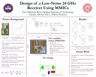
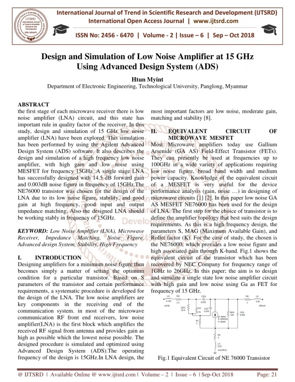
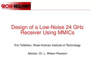
Design of a Low-Noise 24 GHz Receiver Using MMICs. Eric Tollefson, Rose-Hulman Institute of Technology Advisor: Dr. L. Wilson Pearson. Overview. Project Description and Background Introduction to Noise System Overview Microwave Components Design Results Future Work Acknowledgements.

E N D
Design of a Low-Noise 24 GHz Receiver Using MMICs Eric Tollefson, Rose-Hulman Institute of Technology Advisor: Dr. L. Wilson Pearson
Overview • Project Description and Background • Introduction to Noise • System Overview • Microwave Components • Design • Results • Future Work • Acknowledgements
Project Background • 23.6-24 GHz is a “quiet” band • Used for passive sensing of water vapor • Making measurements of manmade signals present from 23.3-24.3 GHz • 24.0-24.25 GHz is an ISM band • For maximum sensitivity, the receiver must have as little noise as possible • Previous design had noise figure of 6-8 dB • Want to redesign for a newer first-stage amplifier with better noise performance
Introduction to Noise • Noise is a natural phenomenon present everywhere • White noise has Gaussian distribution and equal power at all frequencies • Often referred to as AWGN – Additive White Gaussian Noise • A source can be modeled by a noisy resistor at temperature Te: • All components can also be characterized by an equivalent noise temperature:
Noise Figure • Noise Figure (F) is another way of expressing noise • Defined as the reduction in signal-to-noise ratio: • Can also be calculated from the equivalent noise temperature: • For a lossy component at To=290K, the noise figure is equal to the attenuation in the component:
Noise in Systems • Most real systems are a series of individual components in cascade • Can be represented by an equivalent network: • The noise figure and equivalent temperature of the cascade is: • The characteristics of the first component dominate the system • In a low-noise system, the first amplifier stage is key G1 F1 Te1 G2 F2 Te2 G1G2 Fcas Te,cas
System Overview Current System Design (J. Simoneau) Amplifier to be replaced
Transmission Lines • T-lines are efficient conductors of RF energy and inefficient radiators • Come in balanced and unbalanced forms • Coaxial cable is a common form of unbalanced line • T-lines have a characteristic impedance • Normally must be matched to other components • 50 Ω is the most common • Mismatches at junctions create reflections • Represented by Γ, the reflection coefficient:
Microstrip Construction • Microstrips are another form of transmission line • Circuit is created in copper over substrate and ground plane • Substrate is dielectric material, usually low-loss • Shape determines electrical characteristics • Strip width determines characteristic impedance • Open-ended stubs add reactance • Stubs can also provide virtual short circuits to ground • Combinations form filters, impedance transformers, etc. Substrate Copper
Fujitsu LNA MMIC • Monolithic Microwave Integrated Circuit • Fujitsu FMM5701X • Wide bandwidth: 18-28 GHz • High gain: 13.5 dB @ 24 GHz • Low noise figure: 1.4 dB @ 24 GHz • Requires external matching and bias circuitry • Difficult to perform out-of-circuit testing 520 μm 450 μm
Design of Matching Networks • For maximum gain, amplifier input should be conjugate matched (Γin= ΓL*) • For optimum noise performance, amplifier input must see a specified reflection coefficient (Γin= Γopt) • Chose to optimize for noise performance • Used single-stub tuner to match 50 Ω to Γopt • Used quarter-wave transformer to match amplifier output to 50 Ω line
Design of DC Bias Tees • Amplifier is powered by DC bias injected into RF input and output pins • Must design circuitry to provide RF isolation from the DC source and block DC from the RF signal path • Used radial stubs to provide virtual RF short to ground • Used λ/4 sections to transform short into open at transmission line • Will use coupled lines in future versions to block DC from RF connections
Completed Design Bias Tees MMIC Single-stub tuner Quarter-wave transformer
Results – S Parameters • Bias Conditions: • VDD=0 V • IDD=0 mA • VGG=-1 V
Results – S Parameters (cont.) • Bias Conditions: • VDD=5 V • IDD=72 mA • VGG=-1 V
Future Work • Troubleshoot to obtain correctly working prototype • Verify that matching design is correct • Measure noise figure and gain parameters • Integrate into complete system • Measure whole-system parameters for comparison with previous design • Take new noise measurements
Acknowledgements • Dr. L. Wilson Pearson • Joel Simoneau • Chris Tompkins • Simoneau, J. et al. “Noise Floor Measurements in the Passive Sensor Band (23.6 to 24 GHz)” • Pozar, David. “Microwave Engineering 2nd Ed.” John Wiley & Sons, 1998.