Download
1 / 1
10 likes | 84 Views
Bias Tees. MMIC. Single-stub tuner. Quarter-wave transformer. Eric Tollefson, Rose-Hulman Institute of Technology. Faculty Advisor: Dr. L. Wilson Pearson. Project Background. Results. Bias Conditions: V DD =0 V I DD =0 mA V GG =-1 V.

E N D
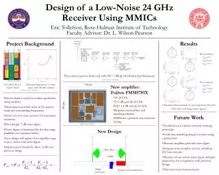
Bias Tees MMIC Single-stub tuner Quarter-wave transformer Eric Tollefson, Rose-Hulman Institute of Technology Faculty Advisor: Dr. L. Wilson Pearson Project Background Results • Bias Conditions: • VDD=0 V • IDD=0 mA • VGG=-1 V The current receiver front-end, with NF=7 dB @ 24 GHz(by Joel Simoneau) Image courtesy of J. Simoneau • Bias Conditions: • VDD=5 V • IDD=72 mA • VGG=-1 V 23.6-24.0 Ghz is a “quiet” band Resonant frequencies of water vapor, with 24 GHz marked 520 μm • New amplifier: • Fujitsu FMM5701X • 18-28 GHz • 13.5 dB gain @ 24 GHz • NF=1.4 dB min @ 24 GHz • Requires external bias and matching circuitry • Difficult to perform out-of-circuit testing Images courtesy of J. Simoneau Design of a Low-Noise 24 GHz Receiver Using MMICs • Passive band is used for weather prediction using satellites • Measuring man-made noise in the passive band and surrounding frequencies • Need very low noise receiver for maximum sensitivity • Prior design: 7 dB noise figure • Noise figure is dominated by the first stage amplifier (see equation below) • New design will replace first amplifier stage to get a lower total noise figure • Improvement should be about .6 dB over previous design S-Parameter Measurements of prototype from 23.6-24.0 GHz (blue) and design values (green) 450 μm Future Work Image courtesy of Fujitsu • Troubleshoot to obtain correctly working prototype • Verify that matching design is correct using s-parameters • Measure amplifier gain and noise figure • Integrate into complete system, including DC bias circuitry • Measure whole-system noise figure and gain parameters for comparison with previous design • Take new noise measurements New Design