Prototype System for High-Density TPC Readout: Addressing Data Volume and Architecture Challenges
This document outlines the prototype design for a readout system intended for High-Density Time Projection Chambers (TPCs). It addresses critical issues like packing density and heat loading while detailing the overall system architecture. The method for processing large data volumes from 400 optical fibers using a 40 MHz, 12-bit readout approach is discussed, highlighting components such as preamps, ADCs, and FPGAs. Additionally, the paper explores baseline subtraction, zero suppression, and event buffering techniques to enhance system performance.

Prototype System for High-Density TPC Readout: Addressing Data Volume and Architecture Challenges
E N D
Presentation Transcript
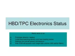
HBD/TPC Electronics Status Works done to for Prototype detector readout Understand packing density and heat loading issues Address the overall system architecture How DCM will process such large data volume (400 optical fibers)
HBD/TPD readout method 40 MHz 12(10) bits 4 msec Preamp /Shaper ADC Baseline Subtr- action L1 Delay buffer Zero Supp- ression 5 Events Buffer ~ factor 10 For TPC only Optical Trigger ? HBD: Preamp/shaper mounted on the pad plane. Signal will be driven to the edge of detector. We would like to measure T0 plus total charge. The longer shaping time will allow us to have several samples at the rising edge of the pulse. We will get 10-20 samples(?) per signal per L1 trigger TPC: Short shaping time (~ 5 samples). 160 samples/channel/L1 trigger to cover 4 microsecond drift time. The preamp + ADC + signal processing will be mounted near the detectors.
New group of Multiple channels ADC Few multiple channel of ADC has came out in the last half years. They have LVDS serialized output. This helps the overall power and size. Analog device: AD9229 4 channel 12bits 50/65 MHz 200mw per channel at 50 MHz, 7mmx7mm size chip scale package AD9289 4 channel 8 bits 65 MHz 65 mw per channel at 65 MHz, 8mmX8mm BGA package TI: 8 channel 12 bits 40 MHz ADC ( to be announced) 100mw per channel, 80 pins PQFP package We have chose the TI’s ADC in the prototype system (no. of channel per chip and low power consumption)
The prototype board • We decide to use the TI 12bits ADC as the starting point. • A readout board configuration as • 8 8-channel ADC + an Altera Stratix FPGA (~1000 pin BGA) (signal processing) + optical chip set • The board should have about 6 “ wide. • The packing density should be reasonable to HBD. • Once we have a preamp/shaper to interface to we can progress further. (i.e. layout the test board)
Signal processing • 8 8 channel ADC requires 8 sets of 8 channel of 480 mps differential LVDS receiver • An ALTERA STRATIX has chosen to interface to ADCs • The FPGA also server as • (code written) • Baseline subtraction • 160 samples(25ns/samples) 4 micro-sec L1 delay – 64 channels • Zero suppression • 5 Level 1 accepted event buffers – 64 channels • Data formatted for the readout • Serial download. • Receive relative timing signals ( L1 accept, Initialize) • (Additional code need to be written) • Test data/pattern • Control for the optical chip set • Busy logic + large event buffers due to zero suppression on the FEM.
What we need to finish the board • Find a connector for the TPC pad plane. • Have a preliminary pad plane signal routing examples for TPC • Funds • We will continue explore the possibility to get a custom chip with multi-channels commercial ADC core + our logics • This is done for ALICE TPC readout • It will be helpful to have consistent R&D fund that devotes to this effort
TPC Data Processing Pad N+1 Pad N pads Pad N-1 time Pad f(n+1) Large signal FPGA Implementation Factor 10 reduction Th 2 Pad f(n) Th 1 An example on how to organized the data Ordered data in for r1 Ordered data in for r35 Pad f(n-1) signal FEM data strip 1 {r1’s…… r35’s} Optical Receiver/buffer buffer buffer Factor 10 reduction FEM data strip x {r1’s…… r35’s} Optical Receiver/buffer buffer buffer