Download
1 / 20
200 likes | 366 Views
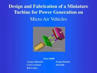
Design and Fabrication of a Miniature Turbine for Power Generation on Micro Air Vehicles. Team 02008 Arman Altincatal Srujan Behuria Carl Crawford Dan Holt Rob Latour. Overview. Project Motivation and Goals Concept Development / Feasibility Assessment

E N D
Design and Fabrication of a Miniature Turbine for Power Generation onMicro Air Vehicles Team 02008 Arman Altincatal Srujan Behuria Carl Crawford Dan Holt Rob Latour
Overview • Project Motivation and Goals • Concept Development / Feasibility Assessment • Project Objectives and Specifications • Analysis • Future Plans
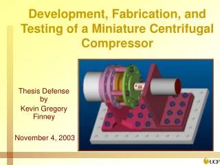
Black Widow by Aerovironment MIT’s Micro Turbine Impeller Current Problem • The weight of batteries is prohibitive for Micro Air Vehicles (MAVs) • Current Batteries • More than 50% of the weight of vehicle • Less instrumentation can be attached to MAV MicroTurbines: a Possible Alternative • Much greater power to weight ratio • Microturbines are being developed at a number of schools
Project Scope • Proof of Concept • 10 mm impeller • Spins at 50,000 rpm • Powered by compressed nitrogen (air) • Produces 5-15 watts of electrical power • Can be scaled down to MEMS size • Distribution of Work
Concept Development and Feasibility • Used Brainstorming Methods to Generate Ideas • After voting, 4 concepts remained: • Multiple Jets • Control Scheme • Air to Cool Generator • Light Weight Materials • Rated the concept feasibility based on technical, economic, market, schedule, and performance factors
Multiple-Jet Concept • Multiple inlets to increase the torque • Total mass-flow must increase • Rotational balance must be achieved • The feasibility of the design is above baseline model (single jet) • The concept is approved by the design team and will be implemented
Control System Concept Development • Terminal Characteristics of a DC Generator • Loading the Generator • Effect of Reduced Shaft Speed • Constant Generated Voltage Desired • Achieving Generator Shaft Speed Control • Variable Solenoid • Variable Nozzle • Control Scheme Feasibility • Above Baseline Aspects • Below Baseline Aspects • Feasibility Assessment Results
Exhaust Air Used to Cool Generator • Cooling Generator • Higher Speeds • More Power • Heat Sink • Friction in Turbine • Reduces Cooling Efficiency • Concept compares well with baseline in most aspects of feasibility • Deferred Decision
Light Weight Materials • Use of light materials • MAV’s • Strength, Cost, Manufacturability • Many options available • Steel, Silicon Carbide, Plastics • Aluminum (Best option) • Team will pursue light weight materials based on feasibility assessment
Design Objectives and Specifications Objectives • Electrical Power • Production of torque • Generator should run for at least 15 minutes • Generator should be reusable • Design for MAV’S • Specifications • 5 watts • Minimum torque should be .021 oz-in • Blades should spin at minimum of 50,000 rpm • Generator Temp. should be less than 125°C
Performance Specifications • Produce at least 5 watts of electrical power • Blades should spin at minimum of 50,000 rpm • Generator Temp. should be less than 125°C • Minimum torque should be .021 oz-in
Flow Passages • Two jet design • Air fitting mounted axially to turbine • Identical Passages • Length, Turns • Inlet Conditions • Head loss calculations • Major, Minor • 7.89% pressure loss (Pinlet =100psi) • Assumptions • Air is an ideal gas • Fully developed, turbulent flow
Nozzle Analysis • Uncontoured converging nozzle design • Nozzle machined into the casing plate • Inlet - 1.58 mm X 1.25 mm • Outlet - 0.7 mm X 1.25 mm • Control volume analysis done for various inlet temperatures and pressures • For Pinlet = 100 psi and Tinlet = 275 K • Mass flow = 0.0048 kg/s • Reaction force = 0.258 lbf • Assumptions • Steady State • Ideal Gas • Isentropic • Choked Flow
Computational Fluid Dynamics • Pre-Processing • Geometry • Mesh • Post-Processing - 2D and 3D Flow Solver • Model Solution • Equations used to solve the model: - Conservation of Mass - Conservation of Energy - Transport Equations (Navier Stokes)
CFD Analysis of Miniature Air Turbine Dynamic Pressure Contours (Pa) • Flow performance - Moving Reference Frame (MRF) - Geometry modifications • Torque due to forces on the blades • Validate CFD with experimental results - Limited references available in this area • Designing a tool to optimize future models Static Pressure Contours (Pa)
Generation • Electrical Scope of Miniature Turbine Project • Generator Selection • Synchronous Generator • Separately Excited DC Generator • Shunt Generator • Series Generator • Permanent Magnet DC Motor (PMDC) • Voltage Regulation Faulhaber Miniature Drive Systems Brushed PMDC Motor Brushless PMDC Motor
Structural Design Inlet Posts Face Plate Turbine Casing Generator Coupling Casing Bolts
Future Plans • Fabrication • Dental Turbine • Experimentation to Validate Objectives and Specifications • Torque, RPM, Exit Temp., Power • Efficiency