Download
1 / 45
470 likes | 821 Views
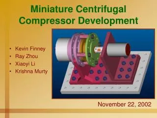
Development, Fabrication, and Testing of a Miniature Centrifugal Compressor. Thesis Defense by Kevin Gregory Finney. November 4, 2003. Presentation Content. Project Specifications What is a Centrifugal Compressor? What makes this compressor unique?

E N D
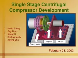
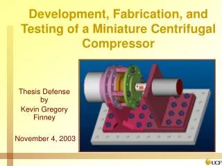
Development, Fabrication, and Testing of a Miniature Centrifugal Compressor Thesis Defense by Kevin Gregory Finney November 4, 2003
Presentation Content Project Specifications What is a Centrifugal Compressor? What makes this compressor unique? Components and procedures for development Motor Bearings Coupler Compressor Part Modeling Compressor Assembly The testing environment / Acquisition of data Results and conclusions from testing
Project Requirements • Reverse Turbo-Brayton cryogenic cooling system for space applications • Goal was to develop a compressor capable of system specifications • Designed inlet conditions • Working fluid was air • Inlet Pressure = 1 atm (14.7 psig) • Temperature = 25o C • Total-to-static pressure ratio of 1.7 required • Mass flow rate of 4.5 grams per second • Led to the design of a centrifugal compressor • Restrictions imposed by entire system • Size of a cola-can / impeller diameter of 4.5 mm • Required the compressor to operate at 150,000 rpm
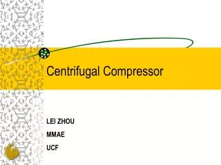
Dynamic compressor Closed volume of fluid does not exist Achieves pressure rise by a dynamic transfer of energy to a continuously flowing fluid stream Fundamentals of a dynamic machine Geometry of Flow Path Direction of Energy Fluid State Liquid = Pump Gas = Fan, Blower, Compressor Definition of Centrifugal Compressor
Characteristics of a Centrifugal Compressor • 1 to 2 = actual compression process • 1 to 2s = isentropic compression = 14.7 psig
Unique Design Characteristics • 150,000 rpm operating speed • Axial flow exiting the diffuser • 4.5 millimeter diameter impeller
Requirements for the Development of Compressor • Material Selection • Weight (inertial forces at high speeds) • Strength (withstand centrifugal stress, hoop stress, and torque) • Feasibility for manufacturing • Cost • Motor Selection • Design required 300 Watts of power at 150,000 rpm • Motor for testing purposes built by Koford Engineering • Bearing Selection • Ball bearings for testing purposes (ceramic balls and cage) • Air foil/journal bearings implemented in future design • Minimal losses in bearing necessary for minimizing power required
Coupler Selection • Alignment (angular, axial, lateral) • Maximum speed • Ability to modify for speed • Availability • Rapid Prototype models • Visual aid during design and machining stages • Manufacturing methods • Parts capable of machining • Manufacturing methods available • Balance of rotating components • Internal parts of motor balanced • Impeller balanced • Balanced at American Hofmann
Motor Characteristics • Torque required at maximum speed was 0.02Nm • 3-phase DC motor via controller with AC supply • Voltage controlled speed • Current drawn determined by torque Design Expectations: Therefore, to obtain the desirable speed and power… A method to remove this heat had to be implemented…
Dispersed Parallel Flow Parallel Flow Motor Motor Chosen due to simplicity in manufacturing the cooling jacket.
Cooling Jacket • Parallel Flow Concept • Pressure loss occurred • one inlet line and six outlet lines • Eliminated possibility of leaks • Turning of fluid occurred in plate • Sealed with Silicone sealant
Bearing Selection • Few bearings available capable of 150,000 rpm • DN Limit (occurred when rotating components involved) • Inner shaft diameter (millimeters) multiplied by the speed (rpm) 10 mm X 150,000 rpm =1,500,000 • Type of lubricant determined by the DN Limit • Maximum DN Limit of 2 million for ‘Barden’ ceramic ball bearing • Expected power loss per bearing important to the amount of power required by motor • Advantages of ceramic bearings • Ceramic Balls versus Steel Balls
Ball Bearing Air Foil Bearing Ceramic balls and cage allowed for higher speed capability Same bearing throughout assembly Expected 50 Watts of loss in each bearing Handled large radial loads compared to axial loads • Very expensive to incorporate • Integrated part of entire design • Only a few manufacturers: Mohawk Innovative Technology, Inc. (MITI) R&D Dynamics Schematic of Foil Bearing courtesy of R&D Dynamics
Coupler Modifications • Modification of coupler for increased speed capability • Stainless Steel Sleeve Retainer
Compressor Modeling and Drawings • Modeling of Parts • Pro Engineer • Finite Element Analysis on blade shape to determine loading effect caused by maximum pressure • Assembly of Parts in Design Stage of Development • Interference between components / clearances • Drawings of Parts for Machinist • Complicated curvatures • required the coordinates of the curve • Tolerance of bearing bores critical to the radial stress placed on the balls • Prototyped parts developed • assisted the machine shop with visual aid of complicated geometry
Part Modeling • Complex geometry • Undercut of impeller blades • Complicated manufacturing methods
Max Stress = 1ksi Yield Stress = 75ksi Hub Shroud Concluded that blade will not fail from fluid loading. Load does not include the centrifugal forces.
Compressor Assembly • Compressor Bearing Placement • Bearing Jig Fixtures • Bearing in Diffuser • Bearing in Top Cap • Specific order of assembly • Collector to Diffuser (bearing) • Collector to Housing • Impeller to Diffuser Bearing • IGV to Housing • Top Cap (bearing) to IGV and Impeller
Bearing Jig Fixtures • Interference fit (force) • Arbor Press • Fixtures to hold part • Bushings to press bearings • Expansion fit (heat) • Used if excessive force required and for disassembly • Jig fixtures designed for disassembly
Rapid Prototyping of Parts • Allowed a visual aid during design • Correction of assembly issues / interferences • Supplied the machinist with an aid • Blade shape and complex geometry more understandable • Provided a visual to CNC code
Comparison of prototype parts to manufactured parts Impeller (cast) Inlet Guide Vane Diffuser
Manufacturing of Parts • Impeller cast in Aluminum A356 • Properties of A356 • Used for aircraft and missile components requiring high strength, ductility, and corrosion resistance. • Used for intricate castings such as cylinder blocks, cylinder heads, fan blades, and pneumatic tools • Contains 7% Silicon and traces of Magnesium and Iron. These alloying elements assist in the strength and corrosion properties. • Tensile Strength37ksi • Yield Strength27ksi Properties taken from “Structure and Properties of Engineering Alloys” by Smith
Straight Blade Impeller Similar blade shape except there was no undercut Only required 4-axis CNC More homogeneous material More naturally balanced
Balancing • American Hofmann (Lynchburg, VA) • Balanced to a g-level (ANSI Standard) equivalent of 150,000 rpm • Material was removed in order to re-skew the axis of the hub to the axis of the shaft • Two of the three ‘Curved Blade’ Impellers • ‘Straight Blade’ Impeller Photo courtesy of American Hofmann
Alignment of Assemblies • Motor shaft alignment to the compressor shaft • Axial • Lateral • Angular • Run-out restricted by the radial play in the bearings • Accurate to the accuracy of the measuring tools • 0.0005 inch accurate dial indicators
Adjusting the Alignment • Adjust assembly alignment with shims • By using shims of 0.0005” thickness, shafts were adjustable • More accurate the alignment, more rigid the coupler could act • Resulted in higher operating speeds with less power consumption
The Testing Environment Voltage versus Speed Curve Pressure Transducer Curve Mass Flow Meter Controller Fan Controller Case Reinforced Cage
Components Required for Testing • Motor and Compressor Assemblies • Assembly support brackets • Common base • Instrumentation • Temperature • Thermocouples • Pressure • Calibration curvefor pressure range • Flow (mass flow measurement) • Operating Speed • Digital reader, Oscilloscope, Frequency counter • Input Power • Data Acquisition
Areas of Desired Measurements Pressure and Temperature at Inlet Mass Flow Controller Power Out of Motor Motor Case Temperature Motor Bearing Temperature Pressure and Temperature after Mixer Bearing Temperature Pressure and Temperature at Diffuser Exit Motor Bearing Temperature Power In Bearing Temperature
Order of Testing • Motor Test • Determine ‘Free-spin’ motor data • Compare the speed measurements for accuracy • Develop Voltage versus speed curve • ‘Blank Shaft’ Test • Determine the efficiency of the motor • Determine the loss per bearing • Compressor Test • Determine the efficiency of the compressor • Determine the work of the impeller on the fluid
Motor Test • ‘Free-spin’ operation • Motor shaft spun only • Input variables and shaft speed recorded
‘Blank Shaft’ Test • Motor efficiency = 40% to 70% • 90,000 rpm = 65% with load • Loss per bearing = 105 Watts at 90,000 rpm
Purpose of Blank Shaft • Blank shaft (no hub nor blades) machined for use in determining the power loss in the bearings • Run motor without any attachments and record power supplied to motor. • Assemble entire unit with blank shaft and operate at 150,000 rpm and record power supplied to motor.
Compressor Test • Curved Blade Impeller • 89,485 rpm, 3.13 g/sec, 2.70 psig • Straight Blade Impeller • 93,984 rpm, 5.14 g/sec, 5.05 psig • Video of Compressor Test
Power consumption curves Actual output conditions: 93,984 rpm 1.29 pressure ratio 61.2% isentropic efficiency 5.1 grams per second mass flow rate Compressor Efficiency Dimensional Analysis Plots
Conclusion • Straight Blade Impeller more effective than Curved Blade Impeller • Compressor was on way to design conditions • Pressure ratio of 1.7 • Mass flow rate of 4-8 grams per second • Operating speed of 150,000 rpm • Reduce losses • Improve alignment • Implement laser aligning procedures • Introduce rigid coupler • Incorporate one shaft throughout the assembly • Incorporate air foil bearing / air journal bearing • Only if power consumption remains high
References Barden, “Precision Bulletin-The Effects of High Speed on Ball Bearings” MMG 2.5 5/94. DellaCorte, C. “Performance and Durability of High Temperature Foil Air Bearings for Oil Free Turbomachinery” NASA/TM-2000-209187/REV1. Glenn Research Center, 2000. Koford, Stuart. “MK-Koford Brushless and Brush Motors.” Website. 2003. http://www.koford.com Rimtec, “Motion Control” A Couple of New Ideas. Vic Jha. January/February, 2000. Smith, William F. Structures and Properties of Engineering Alloys, Second Edition. New York: McGraw-Hill, Inc., 1993.