Download
1 / 4
80 likes | 313 Views
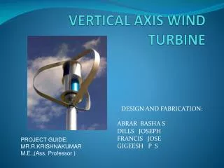
Vertical axis wind turbine uses a radically new approach to capturing wind energy. The device captures the energy of wind and converts it into mechanical form. As the wind bypasses over a turbine blades, the energy will be transferred to the alternator which will exert the force in the down ward direction. These forces are transferred by the belt and pulley arrangement to the battery. The alternator connected is convert wind energy to mechanical energy. Naturally, the design of such device is completely different from a traditional turbine. in horizontal axis wind turbine we use blades, generator and gear which increase the cost of project by 20 of equipment cost. VMWT puts the technology at the very low range of capital intensity for such projects it also makes it highly competitive not only against generations of alternative or renewable energy, but even compared to conventional technologies. This project increases the efficiency than HAWT. Prof. Gaffar G. Momin | Shubham Pawar | Chandrashekhar Patil | Pallavi Deore | Hrushikesh Jagtap "Design and Manufacturing of Vertical Axis Wind Turbine for Power Generation" Published in International Journal of Trend in Scientific Research and Development (ijtsrd), ISSN: 2456-6470, Volume-4 | Issue-4 , June 2020, URL: https://www.ijtsrd.com/papers/ijtsrd31679.pdf Paper Url :https://www.ijtsrd.com/engineering/mechanical-engineering/31679/design-and-manufacturing-of-vertical-axis-wind-turbine-for-power-generation/prof-gaffar-g-momin<br>

E N D
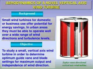
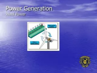
International Journal of Trend in Scientific Research and Development (IJTSRD) Volume 4 Issue 4, June 2020 Available Online: www.ijtsrd.com e-ISSN: 2456 – 6470 Design and Manufacturing of Vertical Axis Wind Turbine for Power Generation Prof. Gaffar G. Momin, Shubham Pawar, Chandrashekhar Patil, Pallavi Deore, Hrushikesh Jagtap Department of Mechanical Engineering, PCCOE, Pune, Maharashtra, India ABSTRACT Vertical axis wind turbine uses a radically new approach to capturing wind energy. The device captures the energy of wind and converts it into mechanical form. As the wind bypasses over a turbine blades, the energy will be transferred to the alternator which will exert the force in the down ward direction. These forces are transferred by the belt and pulley arrangement to the battery. The alternator connected is convert wind energy to mechanical energy. Naturally, the design of such device is completely different from a traditional turbine. in horizontal axis wind turbine we use blades, generator and gear which increase the cost of project by 20% of equipment cost. VMWT puts the technology at the very low range of capital intensity for such projects; it also makes it highly competitive not only against generations of alternative or renewable energy, but even compared to conventional technologies. This project increases the efficiency than HAWT. KEYWORDS: Vertical Axis Wind Turbine, Efficiency, Wind Speed, Blades, Power Generation How to cite this paper: Prof. Gaffar G. Momin | Shubham Chandrashekhar Patil | Pallavi Deore | Hrushikesh Jagtap Manufacturing of Vertical Axis Wind Turbine for Power Generation" Published in International Journal of Trend in Scientific Research and Development (ijtsrd), ISSN: 2456- 6470, Volume-4 | Issue-4, June 2020, pp.1702-1705, URL: www.ijtsrd.com/papers/ijtsrd31679.pdf Copyright © 2020 by author(s) and International Journal of Trend in Scientific Research and Development Journal. This is an Open Access article distributed under the terms of the Creative Commons Attribution License (CC (http://creativecommons.org/licenses/by /4.0) Pawar | "Design and IJTSRD31679 BY 4.0) I. A vertical-axis wind turbine (VAWT) is a type of wind turbine where the main rotor shaft is set transverse to the wind (but not necessarily vertically) while the main components are located at the base of the turbine. This arrangement allows the generator and gearbox to be located close to the ground, facilitating service and repair. VAWTs do not need to be pointed into the wind, which removes the need for wind-sensing and orientation mechanisms. Major drawbacks for the early designs included the significant torque variation or "ripple" during each revolution, and the large bending moments on the blades. Later designs addressed the torque ripple issue by sweeping the blades helically. A vertical axis wind turbine has its axis perpendicular to the wind streamlines and vertical to the ground. A more general term that includes this option is "transverse axis wind turbine" or "cross-flow wind turbine." Today, India is stepping towards becoming a global super power. This implies that, it is leading the list of developing countries in terms of economic development. Hence its energy requirement is going to increase manifold in the coming decades. To meet its energy requirement, coal cannot be the primary source of energy. This is because coal is depleting very fast. It is estimated that within few decades coal will get exhausted. The next clean choice of energy is solar power, but due to its lower concentration per unit area, INTRODUCTION it is very costly. India is having fifth largest installed wind power capacity in the world. As the regions with high wind speed are limited, the installation of conventional windmill is limited. Windmills that would provide safe quiet, simple, affordable and work on lesser wind speeds are need of the hour. Renewable energy is generally electricity supplied from sources, such as wind power, solar power, geothermal energy, hydropower and various forms of biomass. These sources have been coined renewable due to their continuous replenishment and availability for use over and over again. The popularity of renewable energy has experienced a significant upsurge in recent times due to the exhaustion of conventional power generation methods and increasing realization of its adverse effects on the environment. II. Design & Analysis 2.1.CAD Software Computer-aided design (CAD) was used for plotting the design attributes of the model. Having studied all the physical and environmental factors that were to affect the wind turbine, proper elements of the software were used to make sure the model when built is ready to stand firm and sturdy. Computer-aided design (CAD) is the use of computer systems (or workstations) to aid in the creation, @ IJTSRD | Unique Paper ID – IJTSRD31679 | Volume – 4 | Issue – 4 | May-June 2020 Page 1702
International Journal of Trend in Scientific Research and Development (IJTSRD) @ www.ijtsrd.com eISSN: 2456-6470 modification, analysis, or optimization of a design. CAD software is used to increase the productivity of the designer, improve the quality of design, improve communications After the assembling of components on the software the final model came out to look like following. through documentation, and to create a database for manufacturing. Fig.1.1 CAD Model Fig 1.2 Drafted Layout III. ?Belt & Pulley Design 1. Input rpm=2500 rpm. 2. Output rpm=2500 rpm. Now, In our system we want N1=N2, Hence D1=D2-------------(N1=N2=2500 rpm) Here we choose V-belt for better transmission of power with minimum slippage losses. We use V.B. Bhandari -Design data book and R.B. Patil-Transmission system design books as the standards to design the V-belt and pulley system. Calculations @ IJTSRD | Unique Paper ID – IJTSRD31679 | Volume – 4 | Issue – 4 | May-June 2020 Page 1703
International Journal of Trend in Scientific Research and Development (IJTSRD) @ www.ijtsrd.com eISSN: 2456-6470 From Table no-12.23 of DDB (Design Data Book), for N=2500 rpm and P=0.1865 KW we have selected A-type of belt. For A belt- Permissible minimum pitch diameter of pulley=75 mm----------(T.N.-13.23 of DDB) Now, as we want same rpm to be transmitted D=d=75 mm. Centre distance and length of the belt, C.D.=D+d+100----(100 is the allowance value) =75+75+100 C.D. =250 mm Length of the belt, L=2C+π((D1+D2)/2) + (D1 -D2 )2 /4C =2*250+( π150/2)+0 L=735.619mm L=790mm. (design data book, table no.13.25) Total no of belts: For 1 and 2 pulley ………….From design data book page no.-13.18 Fa=1.2-------------------------------- (T.No-13.28) Pr=1.31—---------------------------- (T.No-13.29) Fc=0.84—---------------------------- (T.No-13.34) Fd=1—-------------------------------- (T.No-13.35) No. of belts, Z=(P*Fa)/(Pr *Fc*Fd)-------------(design data book page no.-13.18) Z=0.20=1 Width of pulley, Lmax=(ϰ-1)e+2f (design data book page no.-13.33 =(1-1)e+(2*10) Lmax =20mm Force calculation- From revised edition of transmission system design , chapter no.8 belt,chain,rope drive by auther R.B. Patil and page no. 8-64 For 1 and 2 pulley F1/ F2=eµ’Ɵ µ’= µ/sinβ where, β is the angle of belt, 2β=400……………..(design data book, table no.13.21) µ is the coefficient of friction, µ=0.23 ………(assumed) Ɵ=1800-2α α= sin-1(D-d)/2C ……………………….α=0 Ɵ=1800 F1/F2=8.7932 …………………………………. 1 Now power transmitted by belt, P1 = (F1-F2)V/(1000) V = (πDN)/60*1000 = (π*75*2500)/60*1000 V=9.8125 m/s Hence, F1-F2=18.955----------------------------------------------------2 From 1 and 2, F1=2.432 N--------------- (Slack side) F2=21.387N--------------- (Tight side) So accordingly, we supply 2500 rpm to the alternator. @ IJTSRD | Unique Paper ID – IJTSRD31679 | Volume – 4 | Issue – 4 | May-June 2020 Page 1704
International Journal of Trend in Scientific Research and Development (IJTSRD) @ www.ijtsrd.com eISSN: 2456-6470 IV. ?Turbine Testing: The turbine was tested for the evaluation of the performances without deflectors. In order to do that the height of the three legs of the turbine were increased to make easier the RPM measuring and also to enhance the stability of the turbine. In addition, a simple mechanism was designed and fabricated to take the torque values. Anemometer was used to take the wind speed and Tachometer was used to take the RPM values of the turbine. In the case of testing the turbine a simple brake and a torque measuring mechanism has been introduced. Table 1- Results Testing and Results Rotor power/ W ?Result The turbine has responded the wind speed in a reasonable way. With a wind speed of 6.7 m/s, it has produced around 90W without deflectors. And also with a wind speed of 6.3 m/s, it has produced around 107W with deflectors. It is a good improvement of the power value according to the performances of this Vertical axis wind turbine. V. Conclusion Wind turbine testing was successfully conducted to determine the performance behavior of the 3.5 kW VAWT under ideal wind conditions. The test results showed that the turbine is able to reach its rated power at 14 m/s. The minimum wind speed needed for power production was 6 m/s, and the turbine was tested operationally up to a wind speed of 16 m/s, and with the locked rotor up to 20 m/s. The maximum power coefficient obtained during testing was approximately 0.3, at a tip speed ratio of around 1.6. The turbine is currently undergoing rooftop testing, where in addition to performance measurements, force and vibration measurements will also be performed. VI. Future Scope The future of VAWTs is that they will continue to be a bit player in the small wind generation space, used where aesthetics trump fiscal sense or where green credentials require a visible form of generation. It's hard to point to a situation where it wouldn't be a lot better to deploy solar panels instead of VAWTs. A lot of researchers have developed basic wind turbines, and discover significant parameters that directly involve to changing performances of turbines. Some of them are blade solidity, lift force, drag force and angle of attack. Furthermore, so many researchers have done with considering blade profile. The modern VAWTs occupied blades that developed by NACA which has the ability to self- start. Because of the low self-starting capabilities of the Darrius type turbine, integrate the Savonius type blades by making a hybrid system. This will be very popular use in small generating installations, especially in urban environments that currently have winds that are not exploited. VII. References [1]Sahishnu R. Shah, Rakesh Kumar, Kaamran Raahemifar, Alan S. Fung, “Design, modeling and economic performance of a vertical axis wind Turbine”, Energy Reports 4 (2018) 619623. [2]Abdul Latif Manganhar, Altaf Hussain Rajpar, Muhammad Ramzan Luhur, Saleem Raza Samo, Mehtab Manganhar, “Performance analysis of a savonius vertical axis wind turbine integrated with wind accelerating and guiding rotor house”, Renewable Energy 136 (2019) 512e520. [3]S.M.H. Karimian, Abolfazl Abdolahifar, “Performance Investigation of a New Darrieus Vertical Axis Wind Turbine”, Journal Pre-proof. [4]Antoine Vergaerde, Tim De Troyer, Lieven Standaert, Joanna Kluczewska-Bordier, Denis Pitance, Alexandre Immas, Fr_ed_eric Silvert, Mark C. Runacres, “Experimental validation of the power enhancement of a pair of vertical-axis wind turbines”, Renewable Energy 146 (2020) 181e187 [5]Ammar Naseem, Emad Uddina, Zaib Alia, Jawad Aslama, Samiur Rehman Shaha, Muhammad Sajida, Ali Abbas Zaidi, Adeel Javed, Muhammad Yamin Younis, “Effect of vortices on power output of vertical axis wind turbine (VAWT)”, Technologies and Assessments 37 (2020) 100586. Sustainable Energy @ IJTSRD | Unique Paper ID – IJTSRD31679 | Volume – 4 | Issue – 4 | May-June 2020 Page 1705