Download
1 / 21
1.65k likes | 4.37k Views
Chapter 9 Synthesis and Characterization of Graphene. Bottom-up graphene. 9.1 Chemical vapor deposition 9.2 Epitaxial growth 9.3 Solvothermal. Top-down graphene. 9.4 Micromechanical cleavage 9.5 Chemical synthesis through oxidation of graphite 9.6 Thermal exfoliation and reduction

E N D
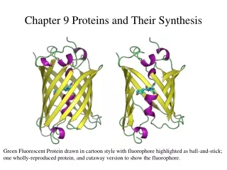
Chapter 9 Synthesis and Characterization of Graphene Bottom-up graphene 9.1 Chemical vapor deposition 9.2 Epitaxial growth 9.3 Solvothermal Top-down graphene 9.4 Micromechanical cleavage 9.5 Chemical synthesis through oxidation of graphite 9.6 Thermal exfoliation and reduction 9.7 Electrolytic exfoliation Characterization 9.8 Characterization
[9-1] Bottom-up graphene In bottom-up processes, graphene can be synthesized by chemical vapor deposition (CVD), arc discharge, epitaxial growth on SiC, chemical conversion, reduction of CO, unzipping carbon nanotubes[9-17], and self assembly of surfactants. CVD and epitaxial growth often produce tiny amounts of large-size, defect-free graphene sheets. However, graphene obtained from the aforementioned method is not suitable for polymer nanocomposites because fabrication of nanocomposites requires a large amount of graphene sheets preferably with modified surface structure. 2
[9-1] Top-down graphene On the other hand, graphite or its derivatives obtained from the top-down methods offers significant economic advantages over the bottom-up methods. Processing for Expanded graphite - Alkali metal- or acid-intercalated graphite can be expanded upon heat treatment to produce a thicker (∼100 nm) form of 2-D carbon known as expanded graphite (EG), which is commonly used as a filler for polymer composites. Recently, a thinner form (∼10 nm) of EG known as graphite nanoplatelets (GNP) was produced by either thermal expansion of fluorinated graphite intercalation compounds or microwave radiation of acid-intercalated graphite followed by pulverization using ball milling or ultrasonication.[@1] Table 2 in Ref. 9-1 provides the summary of top-down processes for producing graphene, CRG and TRG. @1:Because the large diameter and rigidity of graphite flakes are preserved in this process, even without complete exfoliation, GNP can improve electrical conductivity and mechanical properties of polymers at substantially smaller loadings than graphite or EG. 3
9.1 Chemical vapor deposition[9-1, 9-6] Chamber:12-in chamber quartzreactor Heater: graphite electrodes placed at the top and bottom with a separating distance of 10 cm IR detector: temp. measurement Substrate: A cupper foil was placed on the bottom heater Annealing: by H2 and Ar (increase Cu grains) Deposition: using CH4 and H2 as precursor Cooling: rapidly cooling under Ar Mechanisms: 1.Adoption of Cu:(a) low solubility of carbon in Cu, (b) surface diffusion of carbon atoms on Cu; 2.Absorption and de-absorption of hydrocarbon molecules on Cu; 3.Decomposition of hydrocarbon to form carbon atoms; 4.Aggregation of carbon atoms on Cu surface to form graphene nucleation centers; 5.Diffusion and attachment of carbon atoms to nucleation centers to form graphene film 4
Analysis (I): Hydrocarbon precursor and substrate 1.Methane is a relatively stable hydrocarbon compound due to strong C-H bond, as a result, decomposition occurs at elevated temperature (>1200C); 2.Other hydrocarbon compounds such as ethane and acetylene are not suggested due to rapid decomposition at high temperature; 3.Other transition metal such as Fe, Co, and Ni are not preferred for mono or bilayer graphene growth due to their higher-than-desirable capacity to decompose hydrocarbons. 4.The low decomposition rate of methane on Cu allows the possibility of controlling the number of graphene layers. Analysis (II): Decomposition of hydrocarbon 1.Cu foil: Cu foil is usually not single crystal possessing grain boundaries and steps; 2.The sites have much higher chemical activation energy than those of the flat regions of Cu; as a result, hydrocarbons prefer to decompose on the sites to form nucleation centers; 3.Cu foil with smooth surface is preferred: pre-polish and in-situ polish. 5
Schematic of graphene growth process at low-pressure CVD condition: • (1) Nucleation starts at the steps and grain boundaries, • (2) Growth process after nucleation. • (b) Graphene domains on the Cu surface. Arrow indicates the direction of polish lines. • (c) Image of a single tetragonal graphene domain. • (d) OM image of a grown graphene sheet verifying the growth mechanism outlined in (a). 6
Processing parameters-substrate pretreatment 1.Treated by dilute acid 2.Ultrasonic Cu foil in acetone 3.Annealing at lower pressure (due to sublimation of Cu at low pressure) Fig. (a)-(c): Treated in relatively high pressure Fig. (d)-(f): Treated in lower pressure Fig. (g):OM of Fig.(a); (i):OM of Fig.(d), 7
Processing parameters-hydrocarbon concentration • After low pressure annealing, the Cu surface becomes smoother and has low-index planes (such as (1 0 0) plane). due to the restructuring of the Cu atoms enabled by increased diffusivity at high temperatures during the low pressure annealing. • 2. Low partial pressure of hydrocarbon decrease the size of nucleation centers. 8
Processing parameters-purity of the Cu substrate 1.The impurity in the catalyst greatly enhances the catalytic capability of the catalyst. Could the purity of the Cu foil affect the number of layers?* 2.Cu foil with higher purity: 2638–2641 cm-1, I2D/IG:over 3:monolater Cu foil with higher purity: 2641–2646 cm-1, I2D/IG:1.8-2.4:bilayer.** 9
9.2 Epitaxial growth[9-8] • Production of EG on diced (3 mm by 4 mm) • commercial SiC wafers. • Steps: • hydrogen etching to produce atomically • flat surfaces; • (2) vacuum graphitization to produce an ultrathin epitaxial graphite layer; • (3) application of metal contacts (Pd, Au), • (4) electron-beam patterning and • development; • (5) oxygen plasma etch to define graphite structures; • (6) wire bonding. Advantage: Patterned graphene structure 10 Drawback: Ultra-high vacuum, high cost
9.2 Epitaxial growth - SiC decomposition [9-10] Based on the theoretical analysis, stability of the C atoms on SiC substrate was investigated. At a C coverage of 8/3 MLs, corresponding to 8 C atoms on three SiC unit cells, C atoms form a graphene-like two-dimensional sheet and are strongly stabilized.@1 When more C atoms are added, they become highly unstable on the buffer layer and prefer to reside between the buffer layer and SiC substrate. At a C coverage of 16/3 MLs, a new buffer layer is formed at the interface and the original buffer layer loses bonds with the substrate. When SiC substrates are annealed at high temp., Si atoms selectively desorb from the surface and the C atoms left behind naturally form FLG (few-layer graphene) 11
Electrons have wave-like properties, and their kinetic energy determines the wavelength, as shown in Fif. 3(a). Electrons reflected from the graphene surface and graphene/SiC interface can interfere, which causes the electron reflectivity to change periodically as a function of the electron energy and FLG thickness. The LEEM image intensity corresponds to the electron reflectivity. From LEEM images sequentially obtained while the electron beam energy was changed, we obtained the energy dependence of the electron reflectivity from regions 1 to 8, as shown in Fig. 3(e).** 12 Fig. 3(a)~(d) Fig. 3(e)
Growth processes After annealing at 1060ºC, preferential nucleation of the buffer layer occurred at the atomic steps on the SiC surface, where 1/3 of the ML of Si adatoms(@1) was periodically arranged (Fig. 4(a)). After annealing at a higher temperature (Fig. 4(b)), the whole surface was covered with the buffer layer and the surface steps eandered widely(@2). At the initial stage of graphene growth, ML graphene preferentially formed near the substrate steps (Fig. 4(c)). When the annealing temperature was further increased, bilayer (BL) graphene appeared before the buffer layer completely disappeared (Fig. 4(d)). This means that uniform ML graphene is difficult to grow in UHV. 13
Electrical conductivity measurements 1. The nanogap probe contains two Pt electrodes with a gap of 30 nm fabricated at the tip of the cantilever of an atomic force microscopy (AFM) apparatus. 2. An electrical conductivity map of BL graphene is shown in Fig. 5(c). Linear contrasts, which correspond to the substrate steps, reveal that the substrate steps modify the electrical conductivity. 3. The TEM image (Fig. 5a) depicted that FLG covered the substrate steps like a carpet. FLG was locally bent near the steps, and this bending could affect the carrier transport. 14 *
9.3 Solvothermal Facility: 1.Teflon-lined container Materials: 1.Sodium and ethanol with molar ratio of 1:1. Processes: 1.Reaction at 220C for 72 h to form graphene precursor. 2.Rapid pyrolysed and washed using DI water. 3.Vacuum filtration of the suspended solid 4.Dried in a vacuum oven at 100C for 24 h. Mechanism: 1.Under elevated temperature, the alcoholic solution becomes increasingly saturated with the metal alkoxide as it forms, and as a result of the autogenerated pressure (~1 x 10⁻² bar), the free alcohol is encapsulated into the metal alkoxide in a clathrate-like structure. 2.The solid solvothermal product is not purely the ethoxide-ethanol clathrate, some metal hydroxide may also form in the presence of water. 3.Nucleation of sheets occurs around the regions with rich in ethanol. 15
4.Due to the small isolated nature of the trapped ethnol as ignition points, nucleation of the sheets occurs around those regions rich in ethanol. The solid solvothermal product is not purely the ethoxide-ethanol clathrate, some metal hydroxide may also form in the presence of water. A clathrate, clathrate compound is a chemical substance consisting of a lattice that traps or contains molecules. The word clathrate is derived from the Latin clatratus meaning with bars or a lattice. Traditionally, clathrate compounds are polymeric and completely envelop the guest molecule, but in modern usage clathrates also include host-guest complexes and inclusion compounds. According to IUPAC, clathrates are "Inclusion compounds in which the guest molecule is in a cage formed by the host molecule or by a lattice of host molecules.“* 鹽析: 若非極性物質硬是要溶入水溶液中,則水分子會在這些非極性物質的表面,形成一 層比較不活動的隔離層,把非極性物質隔離起來,稱為 clathrate (水籠)。通常水分子 之間,也會以氫鍵互相連結,這些氫鍵會不斷斷裂,然後又很快形成。而水籠的水分 子之間所形成的氫鍵,則較為固定,無法自由去除或生成。 Primary advantages and drawbacks • Simple and possible mass production 16
SiO2 Si 3 nm 3 nm 2.5 nm 0.8 nm SiO2 1.2 nm 9.4 Micromechanical cleavage[9-5] • Fig. 1. Graphene films. • Photograph (in normal • white light) of a large multi- • layer graphene flake on top • of an oxidized Si wafer. • (B) AFM image of 2 mm by • 2 mm area of this flake near • its edge. Colors: dark brown, • SiO2 surface; orange, 3 nm • height above the SiO2 • surface. (C) AFM image of • single-layer graphene. Materials: HOPG Preparation: 1. prepared 5 mm-deep mesas on top of the platelets (mesas were squares of various sizes from 20 mm to 2 mm). 2. Pressed the structured surface on a 1-mm-thick layer of a fresh wet photoresist spun over a glass substrate. After baking, the mesas became attached to the photoresist layer, which allowed us to cleave them off the rest of the HOPG sample. Then, using scotch tape to repeatedly peel flakes of graphite off the mesas.
3. Thin flakes left in the photoresist were released in acetone. 4. Dipping a Si wafer was in the solution and then washed in plenty of water and propanol, some flakes became captured on the wafer’s surface (chose thick SiO2 with t =300 nm). 5. Used ultrasound cleaning in propanol to remove mostly thick flakes. Thin flakes (d < 10 nm) were found to attach strongly to SiO2, presumably due to van der Waals and/or capillary forces. (Left) Optical photograph in white light of a large Hall bar made from multilayer graphene (d »5nm). The central wire is 50mm long. (Right) A short (200 nm) wire made from few-layer graphene. Advantages : Production of single layer graphene is feasible Drawbacks : Limited quantity
9.5 Chemical synthesis through oxidation of graphite[9-1, 9-9] The most promising methods for large scale production of graphene are based on the exfoliation and reduction of GO. The commonly adopted method for producing GO is the Hummers method in which graphite is oxidized using strong oxidants such as KMnO4, KClO3, and NaNO2 in the presence of nitric acid or its mixture with sulfuric acid. GO is composed of graphene oxide sheets stacked with an interlayer spacing between 6 and 10 A ° depending on the water content. The model describes GO as built of pristine aromatic “islands” separated from each other by aliphatic regions containing epoxide and hydroxyl groups and double bonds.
C GO contains ketones ( C=O), 6-membered lactol rings, and tertiary alcohol (Figure 4b) in addition to epoxide and hydroxyl groups. GO has an approximate C/O/H atomic ratio of 2/1/0.8. C Although GO can be readily dispersed in water and in organic solvents after chemical modification, graphene oxide is electrically insulating and thermally unstable. Therefore, at least partial reduction of graphene oxide is necessary to restore electrical conductivity. A number of different methods currently exist for the exfoliation and reduction of GO to produce chemically modified graphene. Stable colloids of graphene oxide can be obtained using solvents such as water, alcohol, and other protic solvents combined with either sonication or long stirring. Alternatively, GO can be exfoliated in polar aprotic solvents by reacting with organic compounds. Colloidal graphene oxide or the organically treated version can be chemically reduced producing chemically reduced graphene (CRG) using hydrazine. 20
* Wikipedia 9-1. Macromolecules, Kim 2010 43 6515 (also 10-5) 9-2. Carbon, Wang 2009 3242 9-3. JACS, Wang 2009 9910 9-4. Nature Nanotechnology 2009 4 30 9-5 Science 2004 306 666 9-6 Carbon, Wei Liu 2011 9-7 Nature, Kim 2009 9-8 Science, Berger 2006 312 1191 9-9 Carbon, Ma 2011 49 1550 9-10 NTT Technical Review, Hibino 2010 8 8 1 9-11 Progress in Materials Science, Singh 2011 56 8 9-12 Nature Materials, Emtsev 2009 8 203 9-13 PRL, Ferrari 2006 97 187401 9-14 Advanced Functional Materials, Shin 2009 19 1987 9-15 Carbon Pei 2010 4466 9-16 Carbon Li 2011 3024 9-17 Macromolecular Chemistry and Physics, Du 2012 213 1060 (also 10-6)