Download
1 / 26
330 likes | 612 Views
1. Solar Photovoltaic Theory. 1-1. Basic principles of PV. 1-1.Basic principle of PV. Contents. 1-1. Basic principles of PV 1-1-1. Mechanism of generation 1-1-2. Various type of PV cell 1-1-3. Installation example 1-1-4. Basic characteristic 1-1-5. Case sturdy. Electrode. Reflect-Proof Film.

E N D
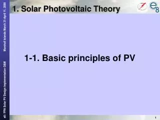
1. Solar Photovoltaic Theory 1-1. Basic principles of PV
1-1.Basic principle of PV • Contents 1-1. Basic principles of PV1-1-1. Mechanism of generation1-1-2. Various type of PV cell1-1-3. Installation example1-1-4. Basic characteristic1-1-5. Case sturdy
Electrode Reflect-Proof Film Solar Energy N-Type Semiconductor Load P-Type Semiconductor - Electric Current + - + Electrode - - + + Photo Voltaic cell 1-1-1. Mechanism of generation • Mechanism of generation The solar cell is composed of a P-type semiconductor and an N-type semiconductor. Solar light hitting the cell produces two types of electrons, negatively and positively charged electrons in the semiconductors. Negatively charged (-) electrons gather around the N-type semiconductor while positively charged (+) electrons gather around the P-type semiconductor. When you connect loads such as a light bulb, electric current flows between the two electrodes.
P • By Solar Energy, current is pumped up from N-pole to P-pole. • In generation, current appears reverse. It is the same as for battery. N P Looks like reverse N 1-1-1. Mechanism of generation • Direction of current inside PV cell • Inside current of PV cell looks like “Reverse direction.” Why? ? Current appears to be in thereverse direction ?
P A N Short Circuit P V N Open Circuit 1-1-1. Mechanism of generation • Voltage and Current of PV cell ( I-V Curve ) • Voltage on normal operation point0.5V (in case of Silicon PV) • Current depend on - Intensityof insolation - Size of cell (A) High insolation Normal operation point(Maximum Power point) Current(I) Low insolation I x V = W (V) Voltage(V) about 0.5V (Silicon)
1-1-1. Mechanism of generation • Typical I-V Curve Depend on cell-size (A) 5.55A Depend onSolar insolation Standard insolation 1.0 kWh/m2 4.95A Depend ontype of cell or cell-material( Si = 0.5V ) Current(I) (V) Voltage(V) 0.62 V 0.49 V
Electric Energy Output x Conversion Efficiency = 100% Energy of Insolation on cell 1-1-2. Various type of PV cell • Types and Conversion Efficiency of Solar Cell Conversion Efficiency of Module 10 - 17% Single crystal Crystalline 10 - 13% Poly crystalline Silicon Semiconductor 7 - 10% Non-crystalline Amorphous Solar Cell Compound Semiconductor 18 - 30% Gallium Arsenide (GaAs) 7 - 8% Dye-sensitized Type Organic Semiconductor Organic Thin Layer Type 2 - 3%
1-1-2. Various type of PV cell • Crystal cell (Single crystal and Poly crystalline Silicon) Single crystal Poly crystalline Formed by melting high purity silicon like as Integrated Circuit For mass production, cell is sliced from roughly crystallized ingot.
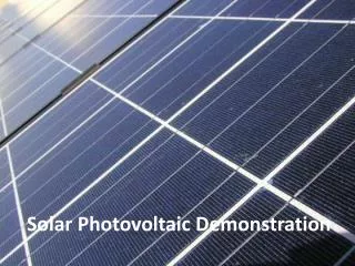
1-1-2. Various type of PV cell • Surface of PV cell • Aluminum Electrode (Silver colored wire) • To avoid shading, electrode is very fine. Example of Poly Crystalline PV Anti reflection film(Blue colored film) Front Surface(N-Type side) • Back surface is P-type. • All back surface is aluminum electrode with full reflection.
1-1-2. Various type of PV cell • PV Module (Single crystal, Poly crystalline Silicon) Single crystal Poly crystalline 120W (25.7V , 4.7A) 128W (26.5V , 4.8A) 1200mm 1200mm (3.93ft) (3.93ft) (2.62ft) Same size 800mm (2.62ft) 800mm Efficiency is lower Efficiency is higher
Volt Ampere Watt Size Cell 0.5V 5-6A 2-3W about 10cm Module 20-30V 5-6A 100-200W about 1m Array 200-300V 50A-200A 10-50kW about 30m 1-1-2. Various type of PV cell • Hierarchy of PV Array 10 - 50 kW Module,Panel 100 - 200 W Cell 2 – 3 W 6x9=54 (cells) 100-300 (modules)
ConferenceRoom(We are now) 20m(66feet) 10m(33feet) 1-1-2. Various type of PV cell • Roughly size of PV Power Station. How much PV can we install in this conference room? Please remember 1 kw PV need 10 m2 (108 feet2) Our room has about 200 m2 (2,178 feet2) We can install about 20 kW PV in this room
1-1-3. Installation example • Roof top of residence ( Grid connected ) Owner can sell excess power to power utility. Most popular installation style in Japan.(Almost 85% PV in Japan )
1-1-3. Installation example • Roof top of school ,community-center building.(For education and emergency power)
1-1-3. Installation example • Distant and independent power supply ( Off grid ) Advertising sign beside highway Relay station on top of mountain
1-1-3. Installation example • Mountain lodge ( Off grid ) Inverter and controller 1.2kW system
1-1-3. Installation example • Stationary power station (Grid connected ) e8 & PPA project in Tuvalu 30kW array 10kW array Site: Funafuti Tuvalu Installation: Feb. in 2008 Capacity: 40kW Purpose: Grid connected power supply for fuel conservation and CO2 reduction.
1-1-3. Installation example • Stationary power station (Off grid or mini grid ) Site: Mongolia Installation: May & June in 1999 Purpose: For lighting, refrigerator and outlet in a hospital. Solar cell capacity: 3.4kW Wind Power capacity: 1.8kW Inverter capacity: 5kVA
Solar array Solar array Solar array Controller Light Solar array Storage battery 1-1-3. Installation example • Solar Home System (SHS)
A V P (A) • “Power conditioner” (mentioned later) will adjusts to be most suitable voltage and current automatically. P1 N PMAX I/V curve Ipmax P- Max control I x V = W Power curve Current(I) P2 (V) Voltage(V) Vpmax 1-1-4. Basic Characteristic • I / V curve and P-Max control • To obtain maximum power, current control (or voltage control) is very important.
If the load has 0.05 ohm resistance, cross point of resistance character and PV-Character will be following point. Then power is 10x0.5=5 W (A) P 12 10 8 6 4 2 0 A N Current(I) Ohm’s theory Resistance character (V) 0 0.1 0.2 0.3 0.4 0.5 0.6 Voltage(V) 1-1-4. Basic Characteristic • Estimate obtained power by I / V curve PV character( I/V curve )
P P P P 5A Mismatch N N N N (A) 1A High intensity insolation 5A Current(I) 5A BypassDiode 1A Low intensity insolation I x V = W 1A 4A (V) 1-1-4. Basic Characteristic • I / V curve vs. Insolation intensity • Current is affected largely by change of insolation intensity. • Partially shaded serial cell will produce current mismatch. Bypass Diode
Crystalline cell 2%down 0.4 – 0.5 (%/deg) Efficiency (%) Amorphous cell 0.25 (%/deg) Summer timeon roof top(65C) Typical(25C) Module Temperature (deg.C) 1-1-4. Basic Characteristic • Temperature and efficiency • When module temperature rises up, efficiency decreases. • The module must be cooled by natural ventilation, etc.
P P P N N N 1-1-5. Case sturdy 1.Maximum power control Q : Calculate how much power you can get by following three resistance. ( I / V curve is next page)
(A) 12 10 8 6 4 2 0 Current(I) (V) 0 0.1 0.2 0.3 0.4 0.5 0.6 Voltage(V) 1-1-5. Case sturdy 1.Maximum power control I/V curve of current insolation.
1-1-5. Case sturdy 2.Temperature vs. Efficiency Q: There is 50 kW Crystalline PV system. If surface temperature rises from 25ºC to 65ºC, How much the capacity will be?