Download
1 / 32
370 likes | 777 Views
Bone Group Presentation 2/23/06. Bone Biomechanics:. Relating Mechanics Concepts to Bone. Presented by: Jeffrey M. Leismer, MEng Edward K. Walsh, PhD. Introduction. Definitions Statics, dynamics, mechanics of materials, failure Concepts to be learned What are stresses and strains?

E N D
Bone Group Presentation 2/23/06 Bone Biomechanics: Relating Mechanics Concepts to Bone Presented by: Jeffrey M. Leismer, MEng Edward K. Walsh, PhD
Introduction • Definitions • Statics, dynamics, mechanics of materials, failure • Concepts to be learned • What are stresses and strains? • How can knowledge of loads and deformations be used to obtain stresses and strains? • How does bone fail? • Audience background/interests?
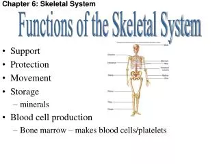
Agenda Ed & Jeff_________________________________________(25 minutes) • Bone mechanics overview • Mechanical influences on the skeleton • Statics • Mechanics of materials • Stress-strain relationship • Mechanical testing • Failure modes in bone Jeff_______________________________________________(5 minutes) • Application: Manatee bone fracture study
BONE MECHANICS Failure (result of loading) Mechanical Testing (response to loading) Statics (equilibrium of forces and moments) Dynamics (bodies in motion) Kinematics (displacements, velocities, and accelerations) Kinetics (forces responsible for motion) Overview BONE MECHANICS Mechanics (effects of forces on a body) To Prof. Walsh
Bone Mechanics Overview To Jeff
Mechanical Influences on the Skeleton • Internal/external loading factors • Loading site, direction, magnitude, speed, repetition, duration • Physiological loading concepts • Muscle forces • Tendon and ligament attachment points • Moment arms (*bicep curl example)
c f b L a q W Mechanical Lever System Mechanical Lever System b=fulcrum d=moment arm F~1/d F d To Prof. Walsh
Vocabulary • Load (N; lbf) • Deformation (mm; in) • Stress (N/m2=Pa; psi) • Strain (mm/mm; in/in) • Moment/Torque (N*m=J; in-lb) • Moment of Inertia (mm4; in4)
Failure (result of loading) Mechanical Testing (response to loading) Mechanics (effects of forces on a body) Kinematics (displacements, velocities, and accelerations) Kinetics (forces responsible for motion) Overview Statics (equilibrium of forces and moments) Statics (equilibrium of forces and moments) Dynamics (bodies in motion)
Statics • Equilibrium of forces ∑F=0 • Equilibrium of moments ∑M=0 • *Bicep curl example To Jeff
c f Rx b d Ry L a q W Static Analysis Static Analysis -To solve for the muscle force, remove rigid body ‘bc’ and replace the section with reaction forces at ‘b’ F
y + ∑Fx=0 q b=90°-q+f =Rx+F*cos(b) Rx=-F*cos(b) f x =F*sin(b)-W+Ry Ry=W-F*sin(b) + ∑Fy=0 q + ∑Mb=0 =W*L*sin(q)-d*F*sin(f) F=W*L*sin(q)/[d*sin(f)] If W=20 lbf, L=14 in, d=0.5 in, q=70°, and f=50°: b=70° F=687 lbf Rx=-235 lbf Ry=626 lbf f Rx b d Ry L a If d=1 in F=343 lbf Rx=-117 lbf Ry=303 lbf q W useful angles Static Analysis Use the figure to find the forces and moments in each direction Now let’s plug in some realistic values and solve for the forces What happens to F if we increase the moment arm, d? Sum the forces and moments and set them equal to zero F Resolve muscle force vector into x and y components To Prof. Walsh
Failure (result of loading) Kinematics (displacements, velocities, and accelerations) Kinetics (forces responsible for motion) Overview Mechanics (effects of forces on a body) Mechanical Testing (response to loading) Mechanics (effects of forces on a body) Statics (equilibrium of forces and moments) Dynamics (bodies in motion)
syy stress cube F tyz tyz tyz tyz txy txy txy txy szz txz txz txz txz F rigid body F sxx Normal Stresses: Bending sb=M*c/I Axial s=F/A sxx txz szz Shear Stresses: Torsion t=T*r/J Transverse Shear t=V/A syy Mechanics of Materials (can be used to show the state of stress at a point) state of stress Types of stresses and their equations To Jeff
c F f Rx b d e Ry L q W Mechanics of Materials Mechanics of Materials -To find the stresses at point ‘e’: -Make a cut at ‘e’ -Remove all components to the right of the cut -Replace the removed section with reaction forces and a moment at point ‘e’ M a
Wy=W*cos(q) ; Wx=W*sin(q) + ∑Fx=0=Rx + ∑Fy=0=-Wy+Ry Ry=Wy + ∑M=0=Wy*(L-d)-M M=Wy*(L-d) If W=20 lbf, L=14 in, d=1 in, and q=70°: M=89 in-lb Rx y e Ry Wx x W Wy Mechanics of Materials Solve for the reaction forces and moment M L-d a q Simplify analysis by rotating the coordinate system and force vectors
ro ri Rx y e Ry Wx x a W Wy Mechanics of Materials Bending stress at ‘e’ due to moment ‘M’ sb=M*c/I c=ro I=p*(ro4-ri4)/4 For M=89 in-lb, ro=0.75 in, ri=0.25 in I=0.245 in4 sb=272 lb/in2 = 272 psi Cross-section of bone at ‘e’ failure strength (bending) << sf=30,250 psi Normal stress at ‘e’ due to Rx sN=Rx/A sN=4.4 psi A=p*(ro2-ri2)=1.57 in2 Rx=Wx=W*cos(q)=6.8 lbf Shear stress at point ‘e’ due to Ry sN=Ry/A sN=12 psi Ry=Wy=W*sin(q)=18.8 lbf M L-d q The stresses found above were calculated for a point at the top of the cross-section. The stresses will be lower at any other point about the cross-section. To Prof. Walsh
Anisotropy (21 elastic constants) • Transverse Isotropy (9 elastic constants) • Orthotropy • Isotropy (2 elastic constants) (5 elastic constants) Stress-Strain Relationship: Constitutive Law Hooke’s Law {s}=[C]{ε} where [C] is the stiffness matrix {ε}=[S]{s}, where [S] is the compliance matrix Inverse relationship [S]=[C]-1 Material properties Elastic modulus = E Poisson’s ratio = u Shear modulus = G To Jeff
Failure (result of loading) Kinematics (displacements, velocities, and accelerations) Kinetics (forces responsible for motion) Overview Mechanical Testing (response to loading) Mechanics (effects of forces on a body) Mechanics (effects of forces on a body) Statics (equilibrium of forces and moments) Dynamics (bodies in motion)
Mechanical Testing of Bone • Handling considerations • Hydration, temperature, strain rate • Types of tests • Tension/compression, bending, torsion, shear, indentation, fracture, fatigue, acoustic • Equipment • Mechanical testing machine, deformation measurement system, recording instrumentation (load-deflection) • Other considerations • Specimen size & orientation, species, sampling location
Ultimate Load X Fracture U Load S Ultimate Displacement Displacement Mechanical Testing • Outcome measures (uniaxial test) • Ultimate load: reflects integrity of bone structure • Stiffness: related to mineralization • Work to failure: energy required to break bone • Ultimate displacement: inversely related to brittleness • Etc.
Failure (result of loading) Kinematics (displacements, velocities, and accelerations) Kinetics (forces responsible for motion) Overview Mechanical Testing (response to loading) Mechanics (effects of forces on a body) Mechanics (effects of forces on a body) Statics (equilibrium of forces and moments) Dynamics (bodies in motion)
Failure of Bone • Failure modes • Ductile Overload Fracture • Failure results from loading bone in excess of its failure strength • Brittle Fracture • Stress is intensified at sharp corners (micro-cracks or voids) and results in fracture without exceeding the failure strength of bone • Creep • Slow, permanent deformation resulting from application of a sustained, sub-failure magnitude load (*Silly Putty™) • Fatigue • Failure due to repetitive loading below the failure strength of bone (a.k.a. stress fractures)
How can this information be put to use? How can this information be put to use? • EXAMPLE • Manatee Bone Fracture Study • 25% of all manatees die as a result of collisions with watercraft • Reducing boat speed in manatee zones can greatly reduce the energy of impact in the event of a collision • Previous researchers correlated the energy associated with traveling at various speeds in a small boat to the energy required to fracture manatee bone • One of the goals of my dissertation work is to build on this information to further reinforce speed restrictions in manatee zones so that this docile creature can remain in existence for future generations to admire • EXAMPLE • Manatee Bone Fracture Study • 25% of all manatees die as a result of collisions with watercraft • Reducing boat speed in manatee zones can greatly reduce the energy of impact in the event of a collision • Previous researchers correlated the energy associated with traveling at various speeds in a small boat to the energy required to fracture manatee bone • One of the goals of my dissertation work is to build on this information to further reinforce speed restrictions in manatee zones so that this docile creature can remain in existence for future generations to admire
Manatee Bone Fracture Study Manatee Bone Fracture Study • Aims • Characterize manatee rib bone • Determine anisotropic fracture properties • Predict the anisotropic stress intensity factors (KI,KII,KIII) using finite element methods and fracture analysis software • Aims • Characterize manatee rib bone • Determine anisotropic fracture properties • Predict the anisotropic stress intensity factors (KI,KII,KIII) using finite element methods and fracture analysis software
proximal 1 3 2 distal Elastic Moduli and Poisson’s Ratios E1, E2, E3, u23, u13, u12 Shear Moduli G23, G13, G12 crack tip Stress Intensity Factors, Fracture Toughness 1) KI, KII, KIII, KIC 2) KI, KII, KIII, KIC 3) KI, KII, KIII, KIC Manatee Bone Fracture Study Rib bone Tension Torsion Compact Tension Tests Specimens Measured Properties
Manatee Bone Fracture Study Manatee Bone Fracture Study • Visual Image Correlation (VIC) 2 cameras take simultaneous pictures of the specimen as it is loaded Correlation software maps the specimen surfaces from the images to digitized 3D space Images of the loaded specimen are used to digitally measure deformations relative the reference photo of the undeformed specimen
Hooke’s Law Orthotropic Compliance Matrix Resulting Strains Due to Applied Stresses Manatee Bone Fracture Study • -Six experiments are run, each with the application of only a single component of stress • From the measured strain, we can calculate all of the orthotropic elastic constants • The elastic constants are used as input to a finite element model for further analysis
Manatee Bone Fracture Study • Finite Element Analysis (FEA) • Computational Fracture Analysis • Crack opening displacements (COD’s) from FEA are used to determine the 3D anisotropic stress intensity factors in a specimen • Numerical results are compared with those from experiment to determine the predictive capacity of the model for fracture analyses
PROFESSOR WALSH AND I WILL NOW TAKE THE REMAINING TIME TO ANSWER YOUR QUESTIONS WE HOPE YOU ENJOYED THE PRESENTATION Resources • Contact Info: • Computational solid mechanics lab (103 MAE-C) • Email Jeff: jeffleismer@gmail.com • Email Ed: ekw@mae.ufl.edu • Books: • Bone Mechanics Handbook (Cowin, 2001) • Mechanical Testing of Bone (An & Draughn, 2000) WE WOULD APPRECIATE YOUR FEEDBACK, SO PLEASE EMAIL US