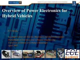
Advanced Demodulator Design and Performance Analysis for Front-End Electronics
This document details the design, testing, and performance outcomes of a new demodulator system for front-end electronics in experimental settings. Key updates include the prototype evolution and improvement in noise performance across operational frequencies. An overview of the proposed changes, such as amplifier redesigns, input noise management, and signal processing optimizations, is provided. Extensive simulation models were employed to enhance overall functionality and meet experimental requirements. The results guide further developments and planning for production phases.

Advanced Demodulator Design and Performance Analysis for Front-End Electronics
E N D
Presentation Transcript
Info on demodulator: http://www.few.vu.nl/organisatie/dienst/technisch/electronica/projects/20062001/ Info on front-end system: http://www.nikhef.nl/pub/departments/et/virgo/ Electronics: Demod + 4Q FE Jo van den Brand, Second V+ review
Design Q2, Q3 2006 Prototype Q1 2007 2+2 Boards Q2 2007 Improvements 2007 Amplifier (noise) PCB length 8.35 MHz (band filter) Demodulator boards Han Voet, VU Amsterdam
RF input: white noise 20 Hz – 20 MHz, 80 mV RMS Test results • Conversion gains • Apply 6.260000 MHz on Ref, 6.260100 MHz on RF • Low 2.75, mid low 25, mid high 230, high 2000 • Cross talk • Apply 6.26 MHZ (8.35 MHz) to both reference inputs. Apply RF signal one channel (vertical/horizontal). • Board 4, 5: H/V I & Q out < 0.3% of V/H • I & Q phase 90 degree phase shift • Measured with a 50 Hz beat frequency output signal on the I & Q outputs • Phase deviation smaller than 1.5 degr • Equivalent input noise • 1 nV/rtHz (to be confirmed) Discussion: replace all demod boards
4Q FE – Modeling Henk Groenstege TINA-TI Multisim
1/f noise amplifier diode cap. resistor noise Modeling • Model agrees with data • DC 2x lower • RF 100 nV/rtHz (was 130 nV/rtHz) • Gives 2.5 pA/rtHz • Optimize both DC and RF
Front-end amplifiers • Non-linear design determined by • Diode • Capacitance • Leakage current • Feedback resistor (white noise) • Feedback capacitance • Desired bandwidth • Desired gain factor • 1/f noise • Amplifier • Voltage noise • Current noise • Input capacitances • Gain-bandwidth product • Under consideration • OPA 846 • OPA 657 • AD 8675 (6V) • ADA 4899-1 • AD 829 Avoid switching in front-end (stray capacitance)
Si PIN YAG 444-4AH 11 mm diameter 0.45 A/W Rev. bias 180 V (power!) 10 pF Si Centronic QD50-3T IR enhanced 0.22 A/W Rev. bias 15 V (GEO) InGaAs Q3000 3 mm diameter 0.90 A/W Rev. bias 10 V < 225 pF 24 ns rise time Photo diodes In discussion with various suppliers: OSIOptoelectronics Centronic Hamamatsu
InGaAs • Simulation • Unacceptable performance at 6 Mz • Bandwidth limited < 400 kHz • InGaAs • 3mm diameter type? • Ordered: will be tested
4Q FE: outside • Dimensions of box roughly the same (48 * 100 * 170 mm) • Mounting tube (30 mm) on front • Same connectors and supply and steering voltages • Bias control & monitoring • New LF outputs • Same detector (YAG 444-4), but rotated to + orientation • Simple overload indication (LEDs) • Spares: orientation x • New: orientation +
4Q FE: inside • Total redesign (old → new): • First stage 2 kV/A → 10 kV/A • DC output amp. 5*, roll off at 100 Hz to 1*, passive pole at 35 Hz (if load > 50 kΩ) → cable driver 1*, pole at 100 kHz. • Extra LF outputs, 1 Hz to 100 kHz. • HF outputs amp. 20*, second order high pass 30 kHz, assumed BW 25 MHz → amp. 4*, 800 kHz … 25 MHz. • Bias monitor • Output with a scale -1/40, -200 V bias gives +5V.
Status / issues • Front-end electronics • No switching in transimpedance stage • Two FE versions • Low power: ≤ 3 mW • High power: ≤ 30 mW • Switching possible after first stage • DC filter 3.3 kHz LP • Prototypes have been constructed • Detector board, with first stage pre-amp • Driver board • contains the cable drivers • differential amplifiers for the hor. and vert. outputs • bias generation, etc • Further studies ongoing • Improve performance • Decide on configuration • Decisions needed on switching DC and RF • Anticipate meeting in January 2008
Discuss switching, etc. Planning Replacement of demodulator boards
Summary • Demodulator boards • First systems delivered • Discuss production of additional boards • Front-end electronics • Simulation models in place • Amplifiers • Diodes • Test performance • Planning • Delivery prototype in March 2008 • Delivery all boards in July 2008
Results 1/f Affected by C Noise R2 Noise R1
Noise sources • Resistors R1 and R2 (10 k) • Noise = 4R kT BW = 4(10.000)(1.38 10-23 J/K)(295 K)(1 Hz) = 1.6 10-16 V2 • Low pass filters • fR1 = 1/2R1C2 = 1/2 (10.000 )(1.5 10-12 F)=10.6 MHz • fR2 = 1/2R2C1 = 1/2 (10.000 )(10 10-9 F)=1.6 kHz • Diode noise • Dark current 1nA (use 180 G on –180V) • Diode capacity 10 pF • Amplifier noise • Use pspice amplifier model • Includes 1/f noise, etc.