Download
1 / 17
200 likes | 589 Views
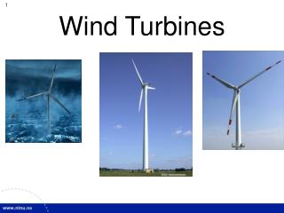
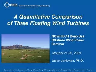
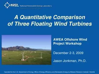
A Quantitative Comparison of Three Floating Wind Turbines. AWEA Offshore Wind Project Workshop December 2-3, 2009 Jason Jonkman, Ph.D. Operated for the U.S. Department of Energy Office of Energy Efficiency and Renewable Energy by Midwest Research Institute • Battelle. Offshore Wind Technology.

E N D
A Quantitative Comparisonof Three Floating Wind Turbines AWEA Offshore Wind Project Workshop December 2-3, 2009 Jason Jonkman, Ph.D. Operated for the U.S. Department of Energy Office of Energy Efficiency and Renewable Energy by Midwest Research Institute • Battelle
Offshore Wind Technology Onshore ShallowWater 0m-30m Transitional Depth 30m-60m Deepwater60m+
Floating Wind Turbine Concepts • Design Challenges • Low frequency modes: • Influence on aerodynamic damping & stability • Large platform motions: • Coupling with turbine • Complicated shape: • Radiation & diffraction • Moorings, cables, & anchors • Construction, installation & O&M
Modeling Requirements • Coupled aero-hydro-servo-elastic interaction • Wind-inflow: • Discrete events • Turbulence • Waves: • Regular • Irregular • Aerodynamics: • Induction • Rotational augmentation • Skewed wake • Dynamic stall • Hydrodynamics: • Diffraction • Radiation • Hydrostatics • Structural dynamics: • Gravity / inertia • Elasticity • Foundations / moorings • Control system: • Yaw, torque, pitch
Floating Concept Analysis Process • Run IEC-style load cases: • Identify ultimate loads • Identify fatigue loads • Identify instabilities • Compare concepts against each other & to onshore • Iterate on design: • Limit-state analysis • MIMO state-space control • Evaluate system economics • Identify hybrid features that will potentially provide the best overall characteristics • Use same NREL 5-MW turbine & environmental conditions for all • Design floater: • Platform • Mooring system • Modify tower (if needed) • Modify baseline controller(if needed) • Create FAST / AeroDyn / HydroDyn model • Check model by comparing frequency & time domain: • RAOs • PDFs
Three Concepts Analyzed NREL 5-MW on OC3-Hywind Spar NREL 5-MW on ITI Energy Barge NREL 5-MW on MIT/NREL TLP
Normal Operation: DLC 1.1-1.5 Ultimate Loads Blade Root Bending Moment Low-Speed Shaft Bending Moment Yaw Bearing Bending Moment Tower Base Bending Moment
Floating Platform Analysis Summary • MIT/NREL TLP • Behaves essentially like a land-based turbine • Only slight increase in ultimate & fatigue loads • Expensive anchor system • OC3-Hywind Spar Buoy • Only slight increase in blade loads • Moderate increase in tower loads; needs strengthening • Difficult manufacturing & installation at many sites • ITI Enery Barge • High increase in loads; needs strengthening • Likely applicable only at sheltered sites • Simple & inexpensive installation
Ongoing Work & Future Plans • Assess roll of advanced control • Resolve system instabilities • Optimize system designs • Evaluate system economics • Analyze other floating concepts: • Platform configuration • Vary turbine size, weight, & configuration • Verify simulations further under IEA OC3 • Validate simulations with test data • Improve simulation capabilities • Develop design guidelines / standards Spar Concept by SWAY Semi-Submersible Concept
Thank You for Your Attention Jason Jonkman, Ph.D. +1 (303) 384 – 7026 jason.jonkman@nrel.gov Operated for the U.S. Department of Energy Office of Energy Efficiency and Renewable Energy by Midwest Research Institute • Battelle
Design Load Case Table Summary of Selected Design Load Cases from IEC61400-1 & -3
Normal Operation: DLC 1.2 Fatigue Loads Side-to-Side Fore-Aft Side-to-Side Fore-Aft Out-of-Plane In-Plane 0° 90° Blade Root Bending Moments Yaw Bearing Bending Moments Tower Base Bending Moments Low-Speed Shaft Bending Moments
Idling: DLC 6.2a Side-to-Side Instability • Aero-elastic interaction causes negative damping in a coupled blade-edge, tower-S-S, & platform-roll & -yaw mode • Conditions: • 50-yr wind event for TLP, spar, & land-based turbine • Idling + loss of grid; all blades = 90º; nacelle yaw error = ±(20º to 40º) • Instability diminished in barge by wave radiation • Possible solutions: • Modify airfoils to reduce energy absorption • Allow slip of yaw drive • Apply brake to keep rotor away from critical azimuths
Idling: DLC 2.1 & 7.1a Yaw Instability • Aero-elastic interaction causes negative damping in a mode that couples rotor azimuth with platform yaw • Conditions: • Normal or 1-yr wind & wave events • Idling + fault; blade pitch = 0º (seized), 90º, 90º • Instability in TLP & barge, not in spar or land-based turbine • Possible solutions: • Reduce fully feathered pitch to allow slow roll while idling • Apply brake to stop rotor