Download
1 / 15
150 likes | 279 Views
IM. Reg. DM. Reg. Stalling delays the entire pipeline. If we delay the second instruction, we’ll have to delay the third one too This is necessary to make forwarding work between AND and OR

E N D
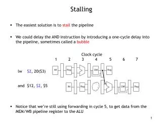
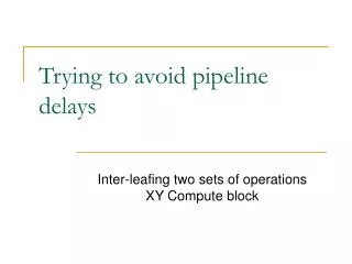
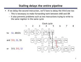
IM Reg DM Reg Stalling delays the entire pipeline • If we delay the second instruction, we’ll have to delay the third one too • This is necessary to make forwarding work between AND and OR • It also prevents problems such as two instructions trying to write to the same register in the same cycle Clock cycle 1 2 3 4 5 6 7 8 lw $2, 20($3) and $12, $2, $5 or $13, $12, $2 IM Reg DM Reg IM Reg DM Reg
IM Reg DM Reg What about EX, MEM, WB • But what about the ALU during cycle 4, the data memory in cycle 5, and the register file write in cycle 6? • Those units aren’t used in those cycles because of the stall, so we can set the EX, MEM and WB control signals to all 0s. Clock cycle 1 2 3 4 5 6 7 8 lw $2, 20($3) and $12, $2, $5 or $13, $12, $2 IM Reg Reg DM Reg IM IM Reg DM Reg
IM Reg DM Reg Stall = Nop conversion • The effect of a load stall is to insert an empty or nop instruction into the pipeline Clock cycle 1 2 3 4 5 6 7 8 lw $2, 20($3) andnop and $12, $2, $5 or $13, $12, $2 IM Reg DM Reg Reg DM Reg IM IM Reg DM Reg
IM Reg DM Reg Detecting Stalls, cont. • When should stalls be detected? EX stage lw $2, 20($3) and $12, $2, $5 mem\wb ex/mem id/ex if/id mem\wb IM Reg Reg DM Reg id/ex ex/mem if/id if/id • What is the stall condition? if (ID/EX.MemRead = 1 and (ID/EX.rt = IF/ID.rs or ID/EX.rt = IF/ID.rt)) then stall
0 1 ID/EX.MemRead Hazard Unit ID/EX.RegisterRt ID/EX 0 IF/ID Write Rs Rt 0 1 EX/MEM WB PC Write MEM/WB M WB PC Control EX M WB IF/ID Read register 1 Read data 1 0 1 2 Addr Instr Read register 2 ALU Zero ALUSrc Write register Read data 2 Result Address 0 1 2 Instruction memory 0 1 Data memory Write data Registers Write data Read data Instr [15 - 0] 1 0 RegDst Extend Rt Rd EX/MEM.RegisterRd Rs Forwarding Unit MEM/WB.RegisterRd Adding hazard detection to the CPU
1 0 0 1 Add Add Branches in the original pipelined datapath When are they resolved? ID/EX EX/MEM WB PCSrc Control MEM/WB M WB IF/ID EX M WB 4 P C Shift left 2 RegWrite Read register 1 Read data 1 MemWrite ALU Read address Instruction [31-0] Zero Read register 2 Read data 2 0 1 Result Address Write register Data memory Instruction memory MemToReg Registers ALUOp Write data ALUSrc Write data Read data 1 0 Instr [15 - 0] Sign extend RegDst MemRead Instr [20 - 16] Instr [15 - 11]
Branches • Most of the work for a branch computation is done in the EX stage: • branch target address is computed • source registers are compared by the ALU, and the Zero flag is set or cleared accordingly • Thus, the branch decision cannot be made until the end of the EX stage • But we need to know which instruction to fetch next, in order to keep the pipeline running! • This leads to what’s called a control hazard Clock cycle 1 2 3 4 5 6 7 8 IM Reg DM Reg beq $2, $3, Label ? ? ? IM
Stalling is one solution • Again, stalling is always one possible solution: • Here we just stall until cycle 4, after we do make the branch decision Clock cycle 1 2 3 4 5 6 7 8 IM Reg DM Reg beq $2, $3, Label ? ? ? IM Reg DM Reg
Branch prediction • Another approach is to guess whether or not the branch is taken: • In terms of hardware, it’s easier to assume the branch is not taken • This way we just increment the PC and continue execution, as for normal instructions • If we’re correct, then there is no problem and the pipeline keeps going at full speed Clock cycle 1 2 3 4 5 6 7 IM Reg DM Reg beq $2, $3, Label next instruction 1 next instruction 2 IM Reg DM Reg IM Reg DM Reg
Branch misprediction • If our guess is wrong, then we would have already started executing two instructions incorrectly. We’ll have to discard, or flush, those instructions and begin executing the right ones from the branch target address, Label. Clock cycle 1 2 3 4 5 6 7 8 beq $2, $3, Label next instruction 1 next instruction 2 Label: . . . IM Reg DM Reg flush IM Reg flush IM IM Reg DM Reg
Performance gains and losses • Overall, branch prediction is worth it: • Mispredicting a branch means that two clock cycles are wasted • But if our predictions are even just occasionally correct, then this is preferable to stalling and wasting two cycles for every branch • All modern CPUs use branch prediction • Accurate predictions are important for optimal performance • Most CPUs predict branches dynamically—statistics are kept at run-time to determine the likelihood of a branch being taken • The pipeline structure also has a big impact on branch prediction: • A longer pipeline may require more instructions to be flushed for a misprediction, resulting in more wasted time and lower performance • We must also be careful that instructions do not modify registers or memory before they get flushed
Implementing branches • We can actually decide the branch a little earlier, in ID instead of EX • Our sample instruction set has only a BEQ • We can add a small comparison circuit to the ID stage, after the source registers are read • Then we would only need to flush one instruction on a misprediction Clock cycle 1 2 3 4 5 6 7 IM Reg DM Reg beq $2, $3, Label next instruction 1 Label: . . . flush IM IM Reg DM Reg
Implementing flushes • We must flush one instruction (in its IF stage) if the previous instruction is BEQ and its two source registers are equal • We can flush an instruction from the IF stage by replacing it in the IF/ID pipeline register with a harmless nop instruction • MIPS uses sll $0, $0, 0 as the nop instruction • This happens to have a binary encoding of all 0s: 0000 .... 0000 • Flushing introduces a bubble into the pipeline, which represents the one-cycle delay in taking the branch • The IF.Flush control signal shown on the next page implements this idea, but no details are shown in the diagram
0 1 0 1 Branching without forwarding and load stalls 1 0 ID/EX EX/MEM WB IF/ID Control MEM/WB M WB PCSrc EX M WB 4 The other stuff just won’t fit! Add P C Shift left 2 Read register 1 Read data 1 ALU Addr Instr Read register 2 Zero = ALUSrc Result Write register Read data 2 Address Instruction memory Data memory Write data Registers Write data Read data 1 0 RegDst IF.Flush Extend Rt Rd
Summary • Three kinds of hazards conspire to make pipelining difficult • Structural hazards result from not having enough hardware available to execute multiple instructions simultaneously • These are avoided by adding more functional units (e.g., more adders or memories) or by redesigning the pipeline stages • Data hazards can occur when instructions need to access registers that haven’t been updated yet • Hazards from R-type instructions can be avoided with forwarding • Loads can result in a “true” hazard, which must stall the pipeline • Control hazards arise when the CPU cannot determine which instruction to fetch next • We can minimize delays by doing branch tests earlier in the pipeline • We can also take a chance and predict the branch direction, to make the most of a bad situation