RC Circuit Delays
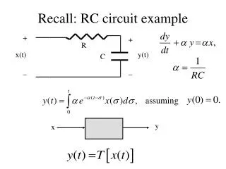
RC Circuit Delays. Shantanu Dutt ECE Dept. UIC. The RC Time Constant. RC Charging Circuit

RC Circuit Delays
E N D
Presentation Transcript
RC Circuit Delays Shantanu Dutt ECE Dept. UIC
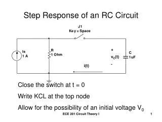
The RC Time Constant RC Charging Circuit The figure below shows a Capacitor, (C) in series with a Resistor, (R) forming a RC Charging Circuit connected across a DC battery supply (Vs) via a mechanical switch. When the switch is closed, the capacitor will gradually charge up through the resistor until the voltage across it reaches the supply voltage of the battery. The manner in which the capacitor charges up is also shown below. RC Charging Circuit Example portion of a digital circuit corresponding to the above RC circuit Cg+Cw • Note: caps in parallel: Vs = Vdd Gate resistance R Icharging Gate i/p cap Cg Wire cap Cw From http://www.electronics-tutorials.ws/rc/rc_1.html (gate pics from http://www.facstaff.bucknell.edu/mastascu/eLessonsHtml/Logic/Logic1.html) (cap pics from http://www.lightandmatter.com/html_books/4em/ch07/ch07.html)
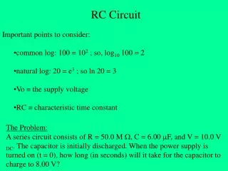
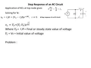
Let us assume that the Capacitor, C is fully "discharged" and the switch is open. When the switch is closed the time begins at t = 0 and current begins to flow into the capacitor via the resistor. Since the initial voltage across the capacitor is zero, (Vc = 0) the capacitor appears to be a short circuit and the maximum current flows through the circuit restricted by resistor R. This current is called the Charging Current and is found by using the formula: i = Vs/R. • The capacitor now starts to charge up with the actual time taken for the charge on the capacitor to reach 63% of its maximum possible voltage, in our curve 0.63Vs is known as the Time Constant, (T) of the circuit and is given the abbreviation of 1T. • So we can say that the time required for a capacitor to charge up to one time constant is given as: • where, R is in Ω's and C in Farads. • The value of the voltage across the capacitor, (Vc) at any instant in time during the charging period is given as: • where: • Vc is the Voltage across the Capacitor • V is the Supply Voltage • t is the elapsed time since the application of the supply voltage • RC is the Time Constant of the RC Charging Circuit The RC Time Constant (contd) RC Charging Curves From http://www.electronics-tutorials.ws/rc/rc_1.html
The RC Time Constant (contd) RC Charging Curves • After a period equivalent to 4 time constants, (4T) the capacitor in this RC charging circuit is virtually fully charged and the voltage across the capacitor is now approx 99% of its maximum value, 0.99Vs. The time period taken for the capacitor to reach this 4T point is known as the Transient Period. After a time of 5T the capacitor is now fully charged and the voltage across the capacitor, (VC) is equal to the supply voltage, (Vs). As the capacitor is fully charged no more current flows in the circuit. The time period after this 5T point is known as the Steady State Period. From http://www.electronics-tutorials.ws/rc/rc_1.html
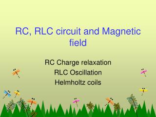
The RC Time Constant (contd) RC Discharging Circuit: In the previous RC Charging Circuit tutorial, we saw how a Capacitor, C charges up through the resistor until it reaches an amount of time equal to 5 time constants or 5T and then remains fully charged. If this fully charged capacitor was now disconnected from its DC battery supply voltage it would store its energy built up during the charging process indefinitely (assuming an ideal capacitor and ignoring any internal losses), keeping the voltage across its terminals constant. If the battery was now removed and replaced by a short circuit, when the switch was closed again the capacitor would discharge itself back through the Resistor, R as we now have a RC discharging circuit. As the capacitor discharges its current through the series resistor the stored energy inside the capacitor is extracted with the voltage Vc across the capacitor decaying to zero as shown below. RC Discharging Circuit From http://www.electronics-tutorials.ws/rc/rc_2.html
In a RC Discharging Circuit, the time constant (T) is now given as the time taken for the capacitor to discharge down to within 37% of its fully discharged value which will be zero volts, and in our curve this is 0.37Vc. As with the previous charging circuit the voltage across the Capacitor, C is equal to 0.5Vc at 0.7T with the steady state fully discharged value being finally reached at 5T. • Then just like the RC Charging circuit, we can say that in a RC Discharging Circuit the time required for a capacitor to discharge itself down to one time constant is given as: • where, R is in Ω's and C in Farads. The RC Time Constant (contd) RC Discharging Curves From http://www.electronics-tutorials.ws/rc/rc_2.html