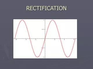

REQUIRING A SPATIAL REFERENCE THE: NEED FOR RECTIFICATION
E N D
Presentation Transcript
Why Rectify? Recall . . . -all attribute data in a GIS must possess a spatial reference -ideally, data from all sources intended for use in the same GIS would share identical datum, projection, ellipsoid, and coordinate properties
Why Rectify? What reference is right? -many datasets have “shifts,” some which are known and documented and some which are not known -metadata is important, from data acquisition, to data handling, and ultimately to data delivery or database management
Standard Rectification Many forms (algorithms): -the most common is polynomial rectification -based on the principles of regression -raw data is forced to fit a reference -can be completed in 2-dimensions (X,Y) or 3-dimensions (X,Y,Z)
Standard Rectification Choosing the appropriate reference data: -data must be at a comparable (suitable) scale -if possible, the phenomena represented by the data should have no spatial- temporal relationship (i.e., the features should not move over time)
Standard Rectification Adding more information . . .
Orthorectification : When an image or photo has been put into an orthogonal plane to Earth by removing camera orientation errors, satellite errors, terrain & relief, etc. Orthorectification Rectification or Geometric Correction : Photos or images have been corrected for incidence error in capturing the data as well geometric error caused by earth rotation
Need for a DEM Digital Elevation Model: - Continuous raster layer in which data file values represent elevation (z-value)
Ortho – Process Overview • Planning and Scanning Photos • Gathering reference information such as lakes, contours, roads, streams, (vectors). • Interpolate DEM (Digital Elevation Model). • Enter Camera Calibration report • Complete Interior points entry • Select GCP’s / or enter known GPS points • Creating automatic Tie points
Ortho Process Cont’d * Model convergence * Examination and Evaluation of the triangulation process. * Color Balancing
Scanning Photos….. Time consuming Important to know the meta data Organization is key Back up as you go, not when you are finished……. Capture all of the fiducial points and make notes of unusual photos or photo orders. Getting Started…..
Digital Elevation Model DEM • There are several ways to create a surface…….. be critical of your product • Some software has problems with contour and elevation data • Interpolation of contours ……non or linear?
Digital Elevation Model Interpolation ??
Camera Calibration Report • Date of calibration • Focal rating • Assessment of lense distortion (fiducial distortion) • Angular distortion • Locations and distances between fiducial points
Interior Control • Bring photos online • Building pyramid layers • Interior control corrects the model to the camera calibration information
Triangulation • Is the mathematical relationship between the photos, the ground and the camera • Traditionally completed using stereo plotters allowing the user to capture ground control points using the control point extension techniques • Digital Triangulation extends the traditional methods to offer: determining image position, determine tie point ground relationships with the overlap, dispersal of error over the block
Block Bundle • Views all of the photo as one image • Allows different types of data to be incorporated into the mosaic • This allows the software to statistically Identify error Distribute error Remove error
Error Checking • Time Robust Error checking • Advanced Robust Error checking • Final error checking (Model is accepted and the points are then moved…..) • ECW compressed trial mosaic product with lakes, and roads coverages.
Color Balancing….. Almost After …. Before
Color Balancing • Masking over exposed areas (CIR) • Buffering lakes and Region growing (Both) • Lakes are essentially lifted out • Final color balancing tweak is completed. • Software--- ER Mapper, Erdas Image Equalizer
Managing Error • Scanning • Different Photo dates • Processing Time • Error assessment • Color balancing • Large files = large hard drives • Projections • Tree shadows, or at the other end of the spectrum lake reflection or significant portions of bedrock • Large lakes
Benefits of an Ortho Mosaic • 1 metre resolution data (color) • Data has been corrected to represent the land base • Excellent Map backdrops when compared to standard line topo - maps • Verification of cut block layout • New GPS units have the capabilities to handling compressed photo back drops.
Benefits of Ortho Mosaics • Each pixel posses geometric properties • Measurements taken from a properly prepared orthorectified product represent the corresponding measurements that would be taken in the field • Updates or additional photos can easily be added to the bundle block model