Dynamically Programmable Array Architecture
Dynamically Programmable Array Architecture. Robert Heaton Obsidian Technology. Mesh of Trees. PU. PU. PU. PU. Busses are BI-directional 2 Cycles to exchange data Separate X and Y dimensions Diagonal routing not directly supported

Dynamically Programmable Array Architecture
E N D
Presentation Transcript
Dynamically Programmable Array Architecture Robert Heaton Obsidian Technology
Mesh of Trees PU PU PU PU • Busses are BI-directional • 2 Cycles to exchange data • Separate X and Y dimensions • Diagonal routing not directly supported • PU’s difficult to program to take advantage of structure PU PU PU PU PU PU PU PU PU PU PU PU
Two Dimensional Mesh PU PU PU PU PU PU PU PU PU PU PU PU PU PU PU PU
4x4 Hierarchical Cluster PU PU PU PU RU RU PU PU PU PU RU PU PU PU PU RU RU PU PU PU PU
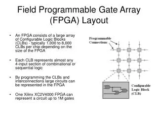
Simple 4x4 Cluster Wiring 6*N Wires Bus width = 140u for 16 bit busses That is a lot of wires! Budget 4x4 Cluster area is 1mm2 Hin1 Hout1 N PU PU PU PU 2L-2 Hadr1 Joint 1.4 M2 Pitch Switch
PU PU PU PU PU PU PU PU PU PU PU PU PU PU PU PU PU PU PU PU PU PU PU PU PU PU PU PU PU PU PU PU PU PU PU PU PU PU PU PU PU PU PU PU PU PU PU PU PU PU PU PU PU PU PU PU PU PU PU PU PU PU PU PU RU RU RU RU RU RU RU RU RU RU RU RU RU RU RU RU RU RU RU RU RU RU RU RU RU RU RU RU RU RU RU RU PU PU PU PU PU PU PU PU PU PU PU PU PU PU PU PU PU PU PU PU PU PU PU PU PU PU PU PU PU PU PU PU PU PU PU PU PU PU PU PU PU PU PU PU PU PU PU PU PU PU PU PU PU PU PU PU PU PU PU PU PU PU PU PU Routing Hierarchy PU PU PU PU PU PU PU PU PU PU PU PU PU PU PU PU RU RU RU RU RU RU RU RU PU PU PU PU PU PU PU PU PU PU PU PU PU PU PU PU RU1 RU1 RU1 RU1 PU PU PU PU PU PU PU PU PU PU PU PU PU PU PU PU RU RU RU RU RU RU RU RU PU PU PU PU PU PU PU PU PU PU PU PU PU PU PU PU • 256 PUs • 4 Levels of hierarchy • Hadr: up level till • L0adr: local address • L1adr: level 1 address • L2adr: level 2 address • L3adr: level 3 address RU2 RU2 RU1 RU1 RU1 RU1 RU3 PU PU PU PU PU PU PU PU PU PU PU PU PU PU PU PU RU RU RU RU RU RU RU RU PU PU PU PU PU PU PU PU PU PU PU PU PU PU PU PU RU1 RU1 RU1 RU1 Hadr L0adr L1adr L2adr L3adr PU PU PU PU PU PU PU PU PU PU PU PU PU PU PU PU RU RU RU RU RU RU RU RU PU PU PU PU PU PU PU PU PU PU PU PU PU PU PU PU RU2 RU2 RU1 RU1 RU1 RU1
Weeks Investigation (9/12/97) • Investigate routing structures • Dynamic routing assignment/programming • Compromise between area and flexibility • Support for tree of trees • Not a complete story yet!
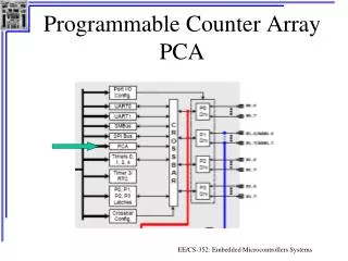
Routing Unit • Full Duplex connect busses • Each PU node controls its source port via a 2 bit local or 6 bit hierarchical address • Broadcast support • Any node may listen to any other input to the cluster • Hierarchical node addressing must not clash Process Unit (PU) Process Unit (PU) Routing Unit (RU) Process Unit (PU) Process Unit (PU)
from port 0 from port 1 from port 2 from port H PU Input N PU Output to other ports N 2 PU Input address 4 6 Routing Unit PU Port Detail • Port numbering is clockwise & relative to each PU port • HBUS port is always at port 3 s0 & s1
PU Overview • Simple data path functionality • Primitive control options • Wide instructions control data path function and operand routing • Conditions may be inverted for “repeat until” or “Branch If” control • Very primitive address arithmetic • 32 or less instructions in program
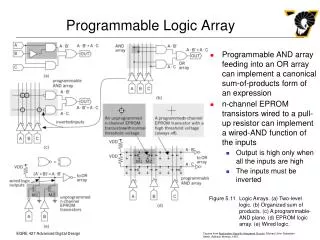
N Bit Functional Unit A • Logic functions: OR, XOR, AND, 0, 1 • Arithmetic: Add, subtract, Multiply • Shifts: single bit left and right • Conditional detection: 0, -1, <0, >0. • More optimization needed • Routing issues need more work Constbit Constbit mux0 mux1 LSin RSin SFTCTL Bit Shift ALUCTL ALU/MULT Cout Cin Carry Logic DFF mux2 F
N Bit Functional Unit (V2) Operands N b it RAM N b it RAM • Logic functions: OR, XOR, AND, 0, 1 • Arithmetic: Add, subtract • Shifts: right and left shifts • Conditional detection: 0, <0, >0, OF • Memory mapped RAM access to operands mux0 mux1 LSin RSin SFTCTL B Shift Multiply Sequencer ALUCTL ALU Cout Cin Carry Logic DFF mux2 Out
Instruction Fields • ?? + XN Bits per context
PU Instruction Types 32 Bits Data Process 00 ALU_CTL, SFT_CTL, MUX_CTL, ROUTE_CTL Move 01 OP_SEL R/W Operand_Value Multiply 100 OP_SEL Options Immediate Operand Attention 101 Condition Branch_Adr Options Flag Branch 110 Condition Branch_Adr Options Link ROUTE_CTL Field: Hadr L0adr L1adr L2adr L3adr Condition Field: Invert +ve -ve zero OF X1 X0 Condition Mask Ext’ Source Sel 15 Bits
Condition Field Condition Field: • X[1:0] are external condition bits & may be source from: • Operand bits • Global synchronization bus • Nearest nabough conditions outputs • Condition Mask is anded with flag bits Invert +ve -ve zero OF X1 X0 Condition Mask Ext’ Source Sel 15 Bits
Static Program • PU Never changes function • Branch is set to always true • Just two Instructions Data Process Always Adr +1 Branch
Open Issues • PU Data path width • Complexity of shift operations • RU Trunking • Number of contexts per PU • Flexible context RAM partitioning • Improve PU synchronization
Design Tools • PU Assembler • Architecture mapping • Global resource allocation
A B Constbit mux0 mux1 LSin RSin SFTCTL Bit Shift ALU/MULT ALUCTL Cout Cin Carry Logic DFF mux2 F Conditional N Bit PU Cell Input Port address RSin LSin RAM ColSel Branch Address Logic Cin EXT[1:0] Condition Logic Cout Out
Commercial Viability • X5 performance improvement over conventional solutions (mix of cost & power) • Conceptually simple • Clearly defined target applications • Simple systems connections • Scaleable • Support hardware & software standards
A B Constbit mux0 mux1 LSin RSin SFTCTL Bit Shift ALU ALUCTL Cout Cin Carry Logic DFF mux2 F Conditional N Bit DPA Cell Routing Matrix 4 Bit Cell: 180 Gates 112 Bits RAM RSin LSin RAM ColSel Routing Matrix Branch Address Logic Cin EXT[1:0] Condition Logic Routing Matrix Cout Routing Matrix
N Bit Wide DPA A B M Plane RAM FU Decode N bit wide FU Program Storage StatusReg Condition Logic C A B M Plane RAM FU Decode N bit wide FU Program Storage StatusReg Condition Logic C A B M Plane RAM FU Decode N bit wide FU Program Storage StatusReg Condition Logic
Status Msk OP Code Source A Source B Shift Op Instruction Format N Bit Wide PU Block PipeBus Local RAM Arbit N Bit wide Shift State HierBus BusW BusX B A Inst RAM Addr Logic I Decode N bit wide ALU Arbit StatusReg Condition Logic NOTES/QUESTIONS - Inst has no const, but has offsets, - Inst RAM can be small. 64 words? - note counter takes 3 instructions. - How much subroutine support? None? - Simplified 16 bit or full 32 bit instructions. - 2 or 4 local area busses? - Synchronization issue: Master states accessible, Cond mask use. - Option to break or combine N bit DP elements? - Resource pool on busses? E.g... MULT? - Approx.. size of 32 bit FU 800u x 500u? - If so a 16x8 processor array is possible. - I.e.. 128 processors at 100MHz = 12800MIPS - Turn off till global state instruction for power reduction - Handling of interrupts (if at all) - Handle global signal interrupts how? - Multiple bit wide segmentation through masks? E.g... 2 counter in one PU? PipeBus
Potential Configuration • 128 32 Bit “Pico” Process Units • 12800MIPS @ 100MHz • 80mm2 in 0.35u CMOS • Concept of hierarchical hardware scope • Very fast streaming operations • Simple PU programming model • Applications: • Video processing • LAN Routing • DSP Fast Prototyping 16 x 8 PU ARRAY Global Ram Controller 256 MUX/DMA/FIFO RAMBUS Interface
PU Program Environment • Operands: BusW, BusX, Accumulator, HierBus, PipeBus, Local Ram. • Use PU Typically runs a small program • May be as little as two instructions • 64 words of code maximum • Instruction types: • Arithmetic, logical • Data moving • Interrupt
Architecture Figures of Merit • Average density vs application specific cells • Speed of applications vs hardwired logic • Percentage reuse
Next Steps • VHDL Modeling of Architecture • Primitive assembler tools for PUs • Selection coding and simulation of applications • Architecture tuning • Layout and verification of complete DPA
Design Tools • Tanner: • Schematic entry, logic simulation, custom layout, layout verification. • Circuit Simulation. • PC & Sun platforms. • MOSIS Libraries. • Mentor Graphics: • VHDL compilation and simulation.
Basic FU Routing FU FU FU FU FU FU FU FU FU FU FU FU