Download
1 / 39
400 likes | 710 Views
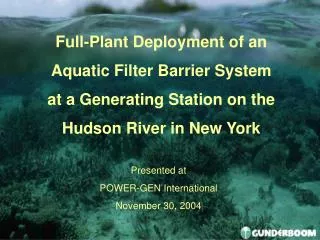
Full-Plant Deployment of an Aquatic Filter Barrier System at a Generating Station on the Hudson River in New York. Presented at POWER-GEN International November 30, 2004. What is an Aquatic Filter Barrier? Purposes and Key Components of a Marine Life Exclusion System (MLES™)

E N D
Full-Plant Deployment of anAquatic Filter Barrier Systemat a Generating Station on the Hudson River in New York Presented at POWER-GEN International November 30, 2004
What is an Aquatic Filter Barrier? Purposes and Key Components of a Marine Life Exclusion System (MLES™) The Lovett Generating Station MLES- Design Fabrication and Installation Lovett MLES 2004 Deployment Overview 2005 Deployment- Challenges and Goals Full-Plant MLES 2004
Aquatic Filter Barrier (AFB) • Full-Depth Underwater Filter • Designed to Exclude Particles, Organisms • Site-Specific Design
Filter Material Strengthening Elements Flotation Devices Mooring System Bottom Seal Aquatic Filter Barrier Components
Aquatic Filter Barrier (AFB) The AFB’s filter material is suspended by flotation billets and is sealed to the bottom by impermeable materials. The seal is optimized by engineering design. Mooring system hardware mounted on the structural skeleton of the AFB provides durable attachment points for the anchor lines, secured to the customized anchors.
AFB Technological Components • Flotation • Protection at Surface • UV Resistant Materials • Bottom Seal • Impermeable Materials • Bottom Chain • Mooring System • Custom-Fabricated Lines • Adjustment Chain
AFB Technological Components • Filter Material • - Non-woven, UV Resistant • - One or Two Layer Concepts • Custom Laser Perforation • Strengthening Elements, The System’s “Skeleton” • - Nylon Strapping • - Structural Netting • - Built-in Sectioning
Marine Life Exclusion System (MLES™) • The MLESTM is an AFB that excludes marine or fresh water organisms from entering a water intake • Designed to exclude aquatic organisms of specific targeted sizes, as small as 200 – 300 microns
Lovett Generating Station • Located on the Hudson River in Tomkins Cove, NY • Three fossil-fueled, steam electric units (Units 3, 4, 5) • Once-through cooling system requiring 391 MGD at full capacity
1995 – Gunderboom System Concept 1996 – Manual AirBurst™/ spud type anchors (3-unit deployment) 1997 – Manual AirBurst™ / dead-weight anchoring system 1998 – Automated AirBurst ™ / 500-micron perforations / monitoring equipment 1999 – Automated AirBurst ™ / monitoring equipment 2000 – Improved field maintenance procedures, mooring hardware and zipper connections Development of MLES™ Technology at Lovett
Site Considerations for MLES™ Development at Lovett • Water Level Fluctuations • Tidal range: 3-5 feet • Currents • Bi-directional up to 2 fps • Waves • Up to 3 feet • Suspended Sediment Loading • Up to 50 mg/L
Site Considerations for MLES™ Development at Lovett • Substrate Quality • Soft, fine sediments • Shell-covered • Steep slope • Potential Fouling Species • Zebra mussels • Characteristics of targeted species
Design Analysis for MLES™ Development at Lovett • Filter fabric surface area requirements • Loading on the AFB and mooring system development • Buoyancy requirements, including ability to fail-safe overtop
Overtopping • Design to relieve pressure under high loading • Initiate at > 2500 pounds • Proportional to Load
Cross Section of MLES™ • Patented “Y” Seal
Construction Design At Lovett, the MLES™ design solution included extending the discharge channels to achieve a greater length of AFB to provide filter fabric area needed for the CWP flow.
AirBurst™ Cleaning System • Automated and redundant cleaning system • Pressurized air cleans fabric cells • Minimal operator requirements
Supervisory Control And Data Acquisition System (SCADA) • Monitors load, water levels, air pressure, flow • Real-time information • Automated cleaning cycles and response
Final Design for the Lovett MLES™ • Addition of sheetpile walls • Alignment of AFB along depth contour • Redundant system of compressed air • Water level sensors and strain gauges to trigger AirBurst™ cycles
August 2003 and March 2004 Fabrication of MLES ™ completed Winter 2003-2004 Sheetpile wall installed Large rocks and boulders removed Anchor tests conducted Anchors installed Pneumatic system/Electrical System installed February-April 2004 Onsite assembly and Installation of AFB Completion of Air Valve Float Boxes Fabrication and Installation Schedule
Custom Laser Perforator • Fabric Apparent Opening Size (AOS) • 150 microns • Fabric Perforation Size • 0.4 mm – 3.0 mm • Proprietary Cross-Web Laser Perforator
Fabrication of AFB • Specialized heat seaming device • Utilized in the attachment of the hood • Custom-manufactured sewing machine
Fabrication of AFB Completed sections of boom, are folded and shipped to site
Sheetpile Installation • Installation of South Mooring Cell • Extension of Unit 3 and 4 discharge
Placement of Anchors • Inside boom area • Twenty-four 32,000 pound concrete cube anchors • Outside boom area • Fifty-six 66,000 pound modified Pearl Harbor anchors
AFB Preparation for Deployment • Billet insertion pockets secured • Curtain is reefed to flotation
AFB Inspection prior to Deployment • AFB unfolded from pallets and laid out onto prepared surface • Flotation billets inserted into the hood • Air hoses are connected
AFB Deployment • Reefed AFB towed into the water
AirBurst ™ Float Assembly • Control boxes attached to AFB • Air line hoses attached
Mooring Connection and Unreefing • AFB is attached to north mooring cell • Anchor lines attached and lengths fine-tuned • Bottom seal inspected after unreefing
Monitored 24/7 by plant operators through HMI Maintenance: Mooring lines tuned Vertical configuration of AFB adjusted Optimized AirBurst™ effectiveness Various adjustments for site characteristics Operations and Maintenance of the Lovett MLES™
Fully-Automated, Including Warnings and Alarms Mirant Lovett provide: 24/7 Monitoring via Human Machine Interface in Control Room Shift inspections and maintenance of Pneumatic and Control Systems Gunderboom provide: Twice daily AFB Inspections Twice Weekly Detailed AFB Boat inspections and Maintenance Regular Dive Inspections and Maintenance Continuous Access and troubleshooting via Remote Access 2004 Deployment – Operations and Monitoring
April 28 to October 31 -- 184 days AirBurst™ Operations – 2 outages over 1 day each One Issue with Additional Consequences – “As-Built” location Less Low-Water Filter Area from Lower Average Depth of Alignment Skirt Failure Required Retrofit on Entire Length of AFB Reduced Cleaning Effectiveness Overtopping to Relieve Strain at Low Water All First-year Challenges Met During Deployment or with Modifications for 2004 2004 Deployment – Serial # 001 – Summary Overview
AFB Deployment in 2005 Design Location No Rocks, Pilings. or Other Riverbottom Hazards in Alignment Increased AirBurst Flexibility and No Outages over 12 Hours Equalize Load on Mooring Points with Limited Mooring Line “Tuning” 2005 Deployment- Challenges and (Preliminary) Goals -- 1 of 2
AFB Configuration Yield Overtopping Upon High Loading, as designed No Major Breaches, Minor Non-Filtering Events Limited to 1 Day Reduce Wear Due to Chafing Limit Time On Site to Monthly Inspections and Planned Maintenance 2005 Deployment- Challenges and (Preliminary) Goals -- 2 of 2
BOOTH 5412*Open House 12/1*Andrew J. McCusker, CEP1Harold B. Dreyer1Melissa A. Hamlin1Shirley B. Ravenna1James C. Campbell, P.E.2 1Gunderboom, Inc. 2Peratrovich, Nottingham & Drage Inc.