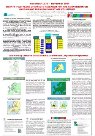
November 2004
November 2004. Beta Iron Disilicide ( b -FeSi 2 ) As an Environmentally Friendly Semiconductor for Space Use.

November 2004
E N D
Presentation Transcript
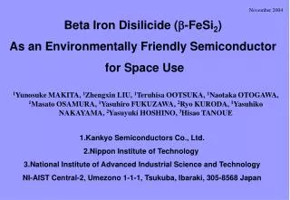
November 2004 Beta Iron Disilicide (b-FeSi2) As an Environmentally Friendly Semiconductor for Space Use 1Yunosuke MAKITA, 1Zhengxin LIU, 1Teruhisa OOTSUKA, 1Naotaka OTOGAWA, 1Masato OSAMURA, 1Yasuhiro FUKUZAWA, 2Ryo KURODA, 1Yasuhiko NAKAYAMA, 2Yasuyuki HOSHINO, 3Hisao TANOUE 1.Kankyo Semiconductors Co., Ltd. 2.Nippon Institute of Technology 3.National Institute of Advanced Industrial Science and Technology NI-AIST Central-2, Umezono 1-1-1, Tsukuba, Ibaraki, 305-8568 Japan
b-FeSi2 Abundance of chemical elements in the earth’s crust
Log C (C=mole/ton Animal Liver Tissue) Log C (C=mole/ton Seawater) Contents of chemical elements in animal liver tissue and seawater
Comparison of b-FeSi2 with Si and GaAs as a photovoltaic semiconductor for space use
Light emitting diode (LED) Photosensor for quartz fiber communication (1.5mm) Thin film solar cell Thermoelectric generator Environmentally friendly semiconductor Properties and possible applications of b-FeSi2 Fe3Si Fe5Si3 Fe2Si Fe-Si compounds e-FeSi Metallic a-Fe2Si5 Semiconductor b-FeSi2 ・Direct band gap: Eg = 0.85 eV ・Optical absorption coefficient: > 105 cm-1 ・Thermoelectric power >10-4 K-1 ・ No-toxicity and abundance of the constituent chemical elements (Fe, Si)
Si(100) b-FeSi2(100) c 2.0% b 5.43Å 1.4% Si(001) b (or c) Si(111) 7.68Å a Si(111) 5.3% 1.4% (2.0) b-FeSi2(101)/(110) Crystal structure of b-FeSi2 Possible epitaxial growth on Si a b c Crystal structure: orthorhombic (Cmca) a=9.86Å, b=7.79Å, c=7.83Å
Electron empty space Electronic density distribution map of b-FeSi2 measured by 4-axis X-ray diffractometerand calculated by MEM Si Fe Owing to a large volume of electron empty space , b-FeSi2 has high resistance against the exposition of cosmic rays and radiation.
1700 1500 Metallic a-Fe2Si5 1410oC 1414oC Possibility of transforming semiconductor b-FeSi2 into metallic a-Fe2Si5 by laser heating 1207oC 1300 1212oC α+ε α+Si 1100 982oC Temperature (oC) 937oC Metallic a-Fe2Si5 can be used as a deposition- and step-free electrode for b-FeSi2 devices. 900 ε b+Si b+ε Semiconductor b-FeSi2 700 500 • 50 60 70 80 90 100 FeSi/Fe Ratio (%) Si Fe-Si phase diagram
Small electronic density cross-sectional area, High resistance against the exposure of cosmic rays and radiation. Thin film solar cell (thinner than 1 mm), Elevation of payload. Use of metallic a-Fe2Si5 as a deposition- and step-free electrode, Improvement of mechanical strength, High reliability at elevated temperatures, Elevation of payload. High resistance against cosmic rays and radiation, Elimination of thick Si substrates, Elevation of payload. Advantages of b-FeSi2 as a photovoltaic semiconductor for space use 1. A large volume of electron empty space. 2. High optical absorption coefficient (>1105cm-1). 3. Semiconductor b-FeSi2 to metallic a-Fe2Si5 phase transformation by laser heating. 4. Growth on stainless steel substrate.
Pole figure of (202)/(220) peak Epitaxial relationship b (101)/(110) b-FeSi2(110) or (101)//Si(111) b (010)/(001) Si(111) Si(110) XRD measurements for b-FeSi2 films grown on Si(111) substrates XRD spectrum
- - High resolution TEM image Si(111) - Si(002) - Si(111) b(220) b(200) b(020) b(110)/(101) Si(111) 0.94nm Interface TEM images of b-FeSi2 films grown on Si(111) substrates Cross-sectional TEM image and diffraction patterns b -FeSi2 b-FeSi2 Si Si
Possible dopants on Si site ・ Substitution at Si sites. ・ Established doping technologies for Si device manufacturing can be used. ・ Expecting high doping efficiencies with low carrier concentrations and high Hall mobilities Impurity doping technologies for b-FeSi2 bulks and thin films p-type n-type Dopants used in thermoelectric devices ・ Substitution at two Fe sites ・ Doping efficiency is very low: ~ several atm % ・ Formation of undesired silicides: MnSi1.7, CoSi2, CrSi2, NiSi2 etc. ・ High residual carrier concentrations: ~ 1020 cm-3 Low mobilities: < 10 cm2/Vs
Effective doping of boron atoms for p-type b-FeSi2 films Boron-doping for p-type b-FeSi2 films
Effective doping of arsenic atoms for n-type b-FeSi2 films Arsenic-doping for n-type b-FeSi2 films
(111) - (110) ‐ - - - (425) (515) Laser light (130) Metallic a-Fe2Si5 (001) a-Fe2Si5 b-FeSi2 a-Fe2Si5 Surface image Metal a-Fe2Si5 electrode b-FeSi2 100nm 200nm Si b-FeSi2 Locally phase-transformed a-Fe2Si5 can be used as a delineated metal contact Phase-transformation from b-FeSi2 to a-Fe2Si5 by laser heating Process image b-FeSi2 n-Si
I-V measurement for a p-b-FeSi2/n-Si heterojunction device a-Fe2Si5 a-Fe2Si5 1mm 1mm p-b-FeSi2 p-b-FeSi2 A 5mm A 5mm n-Si n-Si Metallic a-Fe2Si5 can be used as an electrode for b-FeSi2 devices Phase-transformed a-Fe2Si5 used as an electrode for b-FeSi2 devices Ohmic contact between b-FeSi2 & a‐Fe2Si5
I-V Curve under sun light n-b-FeSi2/p-Si heterojunction solar cell Cell structure Light Electrode n-b-FeSi2 (0.3mm) A p-Si Back electrode Area: 4x4 mm2
XRD spectrum SEM surface image Raman spectrum Formation of b-FeSi2 films on stainless steel substrates Semiconductor b-FeSi2 thin films grow on stainless steel substrates
Wide-gap semiconductors (e. x., ZnO, CuAlO2, etc.) a-Fe2Si5 electrode Metal electrode n-b-FeSi2 Stainless steel Stainless steel p-b-FeSi2 p-b-FeSi2 Buffer layer Structure 1 Structure 2 b-FeSi2 solar cells under development
Small electronic density cross-sectional area, High resistance against the exposure of cosmic rays and radiation. Thin film solar cell (thinner than 1 mm), Elevation of payload. Use of metallic a-Fe2Si5 as a deposition- and step-free electrode, Improvement of mechanical strength, High reliability at elevated temperatures, Elevation of payload. High resistance against cosmic rays and radiation, Elimination of thick Si substrates, Elevation of payload. Summary b-FeSi2 as a semiconductor for space-use solar cell 1. A large volume of electron empty space. 2. High optical absorption coefficient (>1105cm-1). 3. Semiconductor b-FeSi2 to metallic a-Fe2Si5 phase transformation by laser heating. 4. Growth on stainless steel substrate.