Download
1 / 7
70 likes | 187 Views
Detailed guide for setting up IceTop Station, including tank positioning, cable trenching, power requirements, and equipment connections. Follow for smooth installation process.

E N D
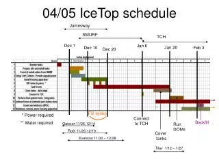
Dec 1 Jan 6 Jan 20 Dec 10 Feb 3 Dec 20 Fill tanks * Power required Connect to TCH Backfill ** Water required Run DOMs Cover tanks 04/05 IceTop schedule Jamesway SMURF TCH Gaisser 11/26-12/14 Roth 11/26-12/19 Evenson 11/30 – 12/28 Tilav 1/12 – 1/27
Surface to DOM Cable From Hole Power Converter (green box) Surface Junction Box Freeze Controller 24VDC +/-48VDC IceTop Excavation Temporary Smurf Cables 2 +/-48VDC Cables 1 RS485 Data Cable Surface Cable from Counting House NOTES: 1. Drawing is in approximate relative scale. 2. Tanks are 10 meters between centers. 3. DOM cables are 17 meters long. 4. RS485 Master source is controlled by plugging in the desired data cable. 5. Tank power source is controlled by plugging in desired power cable. 6. Power Converter contains +/-48VDC to 24VDC converter and EMI filter. George Anderson Sept 17, 2004 File Rev F IceTop Station and Surface Junction Box Interface to IceCube System
C Not to scale A = Tank A B = Tank B C = String/hole J = Junction box Distance AC=BC=25±5 m Distance AB = 10±0.5m Junction box: located between the tanks, exact location TBD on the ice. Cable trench to counting house A B J Tank trench: Ramp-down access from both sides; constant depth between A and B Excess cable: Anywhere between A and B, 1.5 m clearance to tanks To be buried at trench level. Tank positioning
C A = Tank A B = Tank B C = String/hole J = Junction box Distance AC=BC=25±5 m Distance AB = 10±0.5m Junction box: located between the tanks, exact location TBD on the ice. Cable trench to counting house A B J Tank trench: Ramp-down access from both sides; constant depth between A and B Excess cable: Anywhere between A and B, 1.5 m clearance to tanks To be buried at trench level. Freeze-control cables from SMURF until TCH available
Nominal layout of IceTop Minimize deviations from nominal 125 m grid