ENG6090 – VLSI Design
350 likes | 613 Views
Lecture # 1. ENG6090 – VLSI Design. Professor: Shawki Areibi (Off:Thorn 2335) sareibi@uoguelph.ca Lecture Mon - Fri 10:30 - 12:00 pm Thorn2336 Laboratory ENG 2307 (Digital Design Lab) Course Web Page www.uoguelph.ca/~sareibi. COURSE INFORMATION.

ENG6090 – VLSI Design
E N D
Presentation Transcript
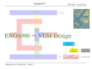
Lecture # 1 ENG6090 – VLSIDesign
Professor: Shawki Areibi (Off:Thorn 2335) sareibi@uoguelph.ca Lecture Mon - Fri 10:30 - 12:00 pm Thorn2336 Laboratory ENG 2307 (Digital Design Lab) Course Web Page www.uoguelph.ca/~sareibi
COURSE INFORMATION Syllabus - VLSI Design/Reconfigurable Computing Grading30% Assign 10% Presentation 40% Project20% Exams Texts - Kang & Leblebici. “CMOS Digital Integrated Circuits” - Rabaey. J. “Digital Integrated Circuits”, 2002 - Uyemura J. P. “Physical Design of CMOS Integrated Circuits Using L-Edit” (optional reference) Project - Cadence Tools - Technology Files (0.18 process) Course Expectations - Must Do a Project to Illustrate your Understanding
ENG6090 – COURSE OBJECTIVES • This course provides an introduction to the fundamental principles of VLSI circuit design. • Emphasis is placed on the design of basic building blocks of large scale digital integrated circuits and systems. • Understand the concept behind ASIC Design. • Implement a complete digital system on silicon using state of the art CAD tools. • Understand the consequence of scaling down the dimensions of transistors and its affect on device speed, density, …. • Have the necessary background to complete CMOS designs and assess which particular design style to use on a given design from FPGA to Full custom design.
ENG6090 TOPICS TO BE COVERED • Overview of VLSI Design Cycle and Methodologies • nMOS, pMOS transistor theory and design equations • Overview of VLSI fabrication technology, • Basic CMOS digital circuits, transistor-level and mask-level design, • Complex logic gates, modular building blocks • Data path components, ASIC design guidelines, • Hardware Descriptive Languages • Reconfigurable Computing Systems (FPGAs) • Physical Design Automation
Integration: Integrated Circuits multiple devices on one substrate How large is Very Large? SSI (small scale integration) 7400 series, 10-100 transistors MSI (medium scale) 74000 series 100-1000 LSI 1,000-10,000 transistors VLSI > 10,000 transistors ULSI/SLSI (some disagreement) VLSI:Very Large Scale Integration
WHY VLSI? • Integration Improves the Design • Lower parasitics, higher clocking speed • Lower power • Physically small • Integration Reduces Manufacturing Costs • (almost) no manual assembly • About $1-5billion/fab • Typical Fab 1 city block, a few hundred people • Packaging is largest cost • Testing is second largest cost • For low volume ICs, Design Cost may swamp all manufacturing cost
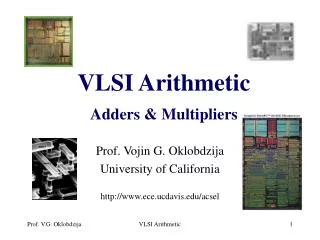
Levels of Design • Specifications • IO, Goals and Objectives, Function, Costs • Architectural Description • VLHD, Verilog, Behavioral, Large Blocks • Logic Design • Gates plus Registers • Circuit Design • Transistors sized for power and speed • Discrete Logic, Technology Mapping • Layout • Size, Interconnect, Parasitics
+ G D S n+ n+ SYSTEM MODULE GATE CIRCUIT DEVICE
MOS = Metal Oxide Semiconductor (This used to mean a Metal gate over Oxide insulation) Now we use polycrystalline silicon which is deposited on the surface of the chip as a gate. We call this “poly” or just “red stuff” to distinguish it from the body of the chip, the substrate, which is a single crystal of silicon. We do use metal (aluminum) for interconnection wires on the surface of the chip. What is “CMOS VLSI”?
G S D D G S Poly crossedoverDiffusion Field effect transistor (FET) Insulated Gate Metal Oxide Semiconductor FET Source and Drain are Interchangeable
Four Terminal Device - substrate bias N-Channel Enhancement mode MOS FET • The “self aligned gate” - key to CMOS
Means we are using both N-channel and P-channel type enhancement mode Field Effect Transistors (FETs). Field Effect- NO current from the controlling electrode into the output FET is a voltage controlled current device BJT is a current controlled current device N/P Channel - doping of the substrate for increased carriers (electrons or holes) CMOS:Complementary MOS
VDD PMOS X X’ NMOS VSS Complementary Metal Oxide Semiconductor
FourViews Logic Transistor Layout Physical
The real issue inVLSI is about designing systems on chips. The designs are complex, and we need to use structured design techniques and sophisticated design tools to manage the complexity of the design. We also accept the fact that any technology we learn the details of will be out of date soon. We are trying to develop and use techniques that will transcend the technology, but still respect it. VLSI Design
Tools Editors Simulators Libraries Module Synthesis Place/Route Chip Assemblers Silicon Compilers Experts Logic design Electronic/circuit design Device physics Artwork Applications - system design Architectures Help from Computer Aided Design tools
Full custom Standard cell Gate-array Macro-cell “FPGA” Combinations Design Styles
Hand drawn geometry All layers customized Digital and analog Simulation at transistor level (analog) High density High performance Long design time Full Custom
Full Custom Vdd IN Out Gnd
Standard cells organized in rows (and, or, flip-flops,etc.) Cells made as full custom by vendor (not user). All layers customized Digital with possibility of special analog cells. Simulation at gate level (digital) Medium density Medium-high performance Reasonable design time Standard cells
Standard cells Routing Cell IO cell
Predefined transistors connected via metal Two types: Channel based Channel less (sea of gates) Only metallization layers customized Fixed array sizes (normally 5-10 different) Digital cells in library (and, or, flip-flops,etc.) Simulation at gate level (digital) Medium density Medium performance Reasonable design time Gate-array
Gate-array Sea of gates Channel based Vdd NAND gate using gate isolation Vdd A B PMOS Oxide isolation B A Out Out NMOS Gate isolation Gnd Can in principle be used by adjacent cell Gnd
Gate-array Sea of gates RAM
Predefined macro blocks (Processors, RAM,etc) Macro blocks made as full custom by vendor All layers customized Digital and some analog (ADC) Simulation at behavioral or gate level (digital) High density High performance Short design time Use standard on-chip busses “System on a chip” Macro cell DSP processor LCD cont. RAM ADC ROM
Programmable logic blocks Programmable connections between logic blocks No layers customized (standard devices) Digital only Low - medium performance (<50 - 100MHz) Low - medium density (up to ~100k gates) Programmable by: SRAM, EEROM, Anti_fuse, etc Cheap design tools on PC’s Low development cost High device cost FPGA = Field Programmable Gate Array
Mixture of full custom, standard cells and macro’s Full custom for special blocks: Adder (data path), etc. Macro’s for standard blocks: RAM, ROM, etc. Standard cells for non critical digital blocks High performance devices
ASIC with mixture of full custom,RAM and standard cells Single port RAM Dual port RAM Full custom Standard cell FIFO
FPGA’s with RAM, PCI interface, Processor, ADC, etc. Gate arrays with RAM, Processor, ADC, etc New combinations Processor FPGA or Gate-array logic RAM