Software Design
Software Design Dr Z He University of Ulster Lecture 4: Software Design Objectives What is Software Design? Data design, architectural design, interface design and component level design Translating the analysis model into a software design Software Design Concepts


Software Design
E N D
Presentation Transcript
Software Design Dr Z He University of Ulster
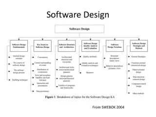
Lecture 4: Software Design • Objectives • What is Software Design? • Data design, architectural design, interface design and component level design • Translating the analysis model into a software design • Software Design Concepts • abstraction, modularity, information hiding • Software Architectural Design • what is software architecture? • Mapping requirements into software architecture • transform flow, transaction flow, transform/transaction mapping • transform mapping • JSD • User Interface Design • what is it?,steps, golden rules • Component-level Design • what is it?, notations (flowchart, decision table, PDL))
What is Software Design? • Software design • sits at the technical kernel of software engineering • begins once software requirements have been analysed and specified • is the first of the three technical activities: design, coding, testing
Software Design • Data design • transforms the information domain model into data structure required to implement the software • also performed in architectural design and component level design • Architectural design • defines the relationship between major structural elements of the software • defines the “design patterns” that can be used to achieve the requirements • defines the constraints that affect the way in which architectural design patterns can be applied • Interface design • describes how the software communicates within itself, to systems that interoperate with it, and with humans who use it • Component-level design • transforms structural elements of the software architecture into a procedural description of software components
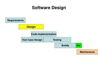
Software Design State transition diagram Component- level Design Process Specification Data Flow Diagram Interface Design Entity-relationship Diagram Architectural Design Data Dictionary Data Design Transforming the analysis model into a software design
Software Design Concepts: Abstraction Design Considerations 1. Abstraction • “Ignore the details that are not relevant at this stage” • 2 types • procedural abstraction • data abstraction • Procedural abstraction • decompose the problem into sub-problems, decompose these into further sub-problems etc. • This ‘top down’ approach leads to modules which are easy to program • sub-problems are ordered logically
Software Design Concepts: Abstraction • Data Abstraction • consider the data only to the level required • e.g. paragraph, sentence, word ... in text processing. • One example of data abstraction is data encapsulation. • e.g. job queue in a compiler. At the top level we know there is a queue and that it has the functions ‘initialise queue’, ‘add to the queue’ and ‘delete from the queue’. At a lower level we might consider how the queue is implemented, as records or arrays. (see later under ‘object oriented design’)
Software Design Concepts: Modularity 2. Modularity • What is module? - a grouping of sections of code. • Pascal - procedure • C - function • Fortran - subroutine • BASIC - subroutine • Cobol - subprogram • Ada - procedure or package Advantages • Easier to design small modules • Easier to find bugs • Easier to maintain • facilitates independent development • allows for reuse
Software Design Concepts: Modularity • How big should a module be? • How complex should a module be? • How can we minimise the interactions between modules? OR
Software Design Concepts: Modularity • What about global data? • Global data is harmful! • To understand A we must know about B & C because of the global data • To change 1 of the modules, if we need to change the data… • Local data is better because • easier to read & study • easier to remove a procedure • maintenance is easier • reusability Global data shared A B C
Software Design Concepts: Modularity Modularity - Cohesion and Coupling (ref Bell et al ch. 5) • Cohesion - the degree of interaction within a module • Coupling - the degree of interaction between modules COHESION • Coincidental Cohesion - tasks which are unrelated • difficult to maintain (no advantage in modularization) • no reusability • Logical Cohesion - tasks in a module are logically related • e.g. all the tasks are to do with input. • interface is difficult to understand • difficult to maintain if code for individual tasks is related
Software Design Concepts: Modularity • Temporal Cohesion - tasks in a module are related by the fact they are done at the same time • e.g. initialisation module • tasks are not related and so if changes are to be made in this module, other parts will have to be changed also. • module’s name may not adequately describe its purpose • Procedural Cohesion - tasks are related because they are done in a sequence. • e.g. read item price, calculate amount due, update stock file • better than temporal since actions are related • but still module is likely not to be reusable since this relation is weak • since all parts of the module do not deal with the same data, it may be difficult to find associated pieces
Software Design Concepts: Modularity • Communicational Cohesion - tasks are related procedurally but also are on the same data. • e.g. read item price, calculate amount due, print total • better than procedural cohesion • still not very reusable • Sequential Cohesion - output of one component of the module forms input for the next. • e.g. read transaction file, update master file (pipe-lined tasks!) • not reusable • Functional Cohesion - All components contribute to a single function of the module. • e.g. calculate VAT (one verb and one noun) • reusable • easily maintained
Software Design Concepts: Modularity • Summary of Cohesion Types (He, Z. Nov. 1999)
Software Design Concepts: Modularity Compute average daily temperatures at various sites Example coincidental functional functional coincidental initialise sums and open files create new temperature record store temperature record close files and print average temperatures logical functional read in site, time, and temperature store record for specific site logical edit site, time or temperature field
Software Design Concepts: Modularity COUPLING • Content Coupling - One module directly affects the working of another. Calling module can modify the called module or refer to an internally defined data element. • e.g. GOTO. • makes maintenance very difficult as program will be difficult to understand. • never allow this type of coupling! • Common Coupling - Two modules accesses the same global data. • E.g. Data division in COBOL • resulting code is difficult to read • side affects e.g has another module changed a variable? • programs are costly to maintain as a change to a global variable means the whole program has to be searched to find its affect • reusability is poor • security problems. A module has access to more data than it needs
Update Stock Level Amend Stock Level transaction code old level new level Software Design Concepts: Modularity • Control Coupling - One module passes information (e.g. flag) which will affect the logic of the other module. • modules are not independent and so reuse is limited • violates principle of ‘information hiding’ (see later) • calling module must ‘know’ how the called module works Remove the flag by having two modules, one for increasing stock level, the other for decreasing stock levels
Software Design Concepts: Modularity • Stamp Coupling - complete data structures are passed from one module to another, with the data structure being defined in both but not all components of the data structure are changed • more data than is necessary is passed • Data Coupling - data required by a module is passed from another (parameters) • Desirable - • HIGH COHESION (functional cohesion) • LOW COUPLING (data coupling)
Software Design Concepts: Information Hiding Information hiding • Each module has information which other modules have no access to • Hence a change to this cannot affect any other module • increases cohesion, since the information hide binds the components of the module together • design decisions that may change at a later date should be hidden from other modules. In this maintainability is increased since only that module needs to ‘know’ about the change
Software Architectural Design • What is software architecture? • The software architecture of a program or computing system is the structure or structures of the system, which comprise software components, the externally visible properties of those components, and the relationships among them. • At the architectural level, internal properties (e.g. details of an algorithm) are not specified • Architectural Styles • Data centred architecture, data flow architecture, call and return architecture, object-oriented architecture, layered architecture • See, Pressman’s book for more
Software Architectural Design • Mapping requirements into a software architecture • Transform Flow • information enter software from external world • external information converted into internal forms (incoming flow) • incoming data are transform (transform centre) • processed data converted for external use (outgoing flow) • information exit software to external world • Transaction Flow • similar to transform flow, but an incoming flow will reach a transaction centre, where one of many paths will be taken. • Transaction flow is characterized by data moving along an incoming path that converts external world information into a transaction. The transaction is evaluated and based on its value, flow along one of many action paths is initiated.
Software Architectural Design • Mapping requirements into a software architecture • Transform Mapping • also called transform analysis • set of design steps that allows a DFD with transform flow characteristics to be mapped into a specific architectural design • you need to identify a transform centre in a DFD • Transaction Mapping • also called transaction analysis • set of design steps that allows a DFD with transaction flow characteristics to be mapped into a specific architectural design • you need to identify a transaction centre in a DFD • In this lecture • we will discuss transform mapping (design method) • also Jackson Structured Development (JSD) (design method)
Transform Mapping Transform Mapping (Bell et al, ch 8) • input is a set of DFDs • Each DFDs represents the transformation of input to output • Input becomes internal data and, later, output • Thus - three modules • INPUT • TRANSFORM • OUTPUT • Each of these is then further decomposed. • This process continues until the module performs a single task (high cohesion)
Transform Mapping Steps: • Identify the central transformations • Draw a top level structure of the module • Factor lower levels
Transform Mapping Example: Customer File transform output input Obtain account number check identity of customer extract account details Calculate balance Format Balance Display Balance account details balance a/c no. valid a/c no. formatted balance Account file Data Flow diagram for a balance enquiry system
Transform Mapping Controlling Module Input Module Transform Module Output Module Standard format for transform analysis
Transform Mapping Obtain Balance Details bal details account details a/c details bal details Calculate Balance Obtain Account Details Display Balance
Transform Mapping Obtain Balance Details = check flag bal details account details a/c details bal details Calculate Balance Obtain Account Details Display Balance a/c details a/c no formatted balance balance a/c no (val) formatted balance a/c no a/c no (val) Obtain account number Check customer identity Extract account details Format Balance Display Balance
Jackson Structured Development • See Bell et al ch 7 • Data oriented • 3 constructs • sequence • iteration and • selection
Jackson Structured Development SEQUENCE ITERATION SELECTION A A A B* B C D BO BO BO • Pseudocode: • A seq • B; • C; • D; • A end • A itr • B; • A end • A sel • B; • A alt • C; • A alt • D; • A end
Process Picture Process Top-half Process Middle Process Bottom-half Process Line* Process Line* Jackson Structured Development • Example 1 • suppose we want a program to produce the output as shown * *** ***** ***** *** * Picture Top-half Middle Bottom-half Line* Line*
Process Picture Process Top-half Process Middle Process Bottom-half Process Line* Process Line* Jackson Structured Development • Next, define elementary operations • Add operations to the diagram 1. Write n asterisks 4. Increment s 7. Decrement n 2. Write a blank line 5. Decrement s 8. Initialise n & s 3. Write s spaces 6. Increment n 8 2 1 5 1 4 3 6 3 7
Jackson Structured Development • Transform into pseudocode: initialise n and s while more lines do write s spaces write n asterisks decrement s increment n end while write blank line initialise n and s while more lines do write s spaces write n asterisks decrement n increment s end while
Jackson Structured Development • Summary of steps • Draw a diagram showing the structure of the data • Derive the corresponding program structure chart • Write down the elementary operations • Place the operations on the program structure diagram • Derive the schematic logic of the program
Numbers Body Negative Number Number * Jackson Structured Development • Example 2 • Design a program to input and add up any number of numbers ending with a negative number Steps: 1. Read number 2. Add number to sum 3. Initialise sum 4. Print sum Process Numbers sum=0 read number while number > 0 do add number to sum read number end while print sum Process Body Process Negative Number 3 1 Process Number * 2 4
Jackson Structured Development • Example 3 • Suppose we have a stock control system that has a menu STOCK CONTROL 1. Issue stock 2. Receive stock 3. Create item 4. Delete item 5. Query item 6. Exit Please enter choice:_ Dialogue Screen * Heading Choices Prompt Response Invalid Valid Wrong * 1 o 2 o Etc. Junk Error msg
Jackson Structured Development While usr choice not = end do clear screen display heading display choices display prompt accept user choice while user choice is wrong do display error msg accept user choice end while case user choice 1: call issue procedure . . 5: call query procedure end case end while • Elementary operations • clear screen • display heading • display choices • display user prompt • accept user response • display error message • call issue procedure • call receive procedure • call create procedure • call delete procedure • call query procedure
User Interface Design • User Interface Design • creates an effective communication medium between a human and a computer • identifies interface objects and actions and then creates a screen layout that forms the basis for an user interface prototype • an iterative process • Steps • identify user, task and environmental requirements • create scenarios which are then analysed to define a set of interface objects and actions • create screen layout (graphics, text, menus, etc) • prototype the design • evaluate for quality
User Interface Design • Golden Rules • Place the user in control • define interaction modes in a way that does not force a user into unnecessary or undesired actions • provide for flexible interaction • allow user interaction to be interruptible and undoable • streamline interaction as skill levels advance and allow the interaction to be customised • hide technical internals from the casual user • design for direct interaction with objects that appear on the screen
User Interface Design • Golden Rules • Reduce the user’s memory load • reduce demand on short-term memory • establish meaningful defaults • define shortcuts that are intuitive • the visual layout of the interface should be based on a real world metaphor • disclose information in a progressive fashion • Make the interface consistent • maintain consistency across a family of applications • do not change past interactive models unless there is compelling reason to do so
Component-level Design • Component-level Design • also called procedural design • occurs after data, architectural, and interface designs • represents the design at a level of abstraction that is close to code • establishes the algorithm detail required to • manipulate data structures, effect communication between software components via their interfaces, • and implement the processing algorithms allocated to each component • Component-level design notations • Flowchart (based on structured programming, Dijkstra, 1960s) • Decision table • Program Design Language (PDL)
Component-level Design • Flowchart (sequence, if-then-else, switch, do-while, repeat-until)
Component-level Design • Decision Table CONDITIONS 1 2 3 4 5 fixed rate account T T F F F variable rate account F F T T F consumption<100kwh T F T F consumption>=100kwh F T F T ACTIONS min. monthly charge X schedule A billing X X schedule B billing X other treatment X
Component-level Design • Program Design Language (PDL) • also called structured English, or pseudocode • looks like programming language, but • use narrative text embedded directly into a syntactical structure • cannot be compiled • could be translated into a programming language “skeleton” or a graphical representation(e.g. flowchart) of design