Download
1 / 25
250 likes | 439 Views
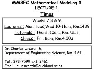
MM3FC Mathematical Modeling 3 LECTURE 2. Times Weeks 7,8 & 9. Lectures : Mon,Tues,Wed 10-11am, Rm.1439 Tutorials : Thurs, 10am, Rm. ULT. Clinics : Fri, 8am, Rm.4.503. Dr. Charles Unsworth, Department of Engineering Science, Rm. 4.611 Tel : 373-7599 ext. 2461

E N D
MM3FC Mathematical Modeling 3LECTURE 2 Times Weeks 7,8 & 9. Lectures : Mon,Tues,Wed 10-11am, Rm.1439 Tutorials : Thurs, 10am, Rm. ULT. Clinics : Fri, 8am, Rm.4.503 Dr. Charles Unsworth, Department of Engineering Science, Rm. 4.611 Tel : 373-7599 ext. 2461 Email : c.unsworth@auckland.ac.nz
This LectureWhat are we going to cover & Why ? • Discrete representation of continuous signals. (because this is how we digitize a signal) • The Running Average Filter. (the simplest form of FIR filter) • The General FIR filter. • Impulse response of a filter. (a way to classify a filter’s characteristics)
Continuous & Discrete Signals • Real world (analogue) signals are “ continuous ” in time. • A ‘continuous sinusoid’ x(t) is represented : • x(t) = Acos(ωt + φ) • Any recorded signal is said to be “discrete ”. • A ‘discrete (digital) signal’ is a ‘snap-shot’ x[n] of a continuous signal taken every (Ts) secs. • x[n] = x(t) with t= nTs x[n] = Acos(ω(nTs) + φ) • Where, (n) is an integer indicating the position of the values in the sequence. … (2.1)
x[n] Input Discrete Time System T{ } y[n] = T{x[n]} Ouput Discrete-Time (Digital) Filters • A ‘digital filter’ - takes in a digital ‘input signal’ x[n]. - alters it in some way, by an operation T{ }. - And creates a digital output signal y[n] = T{x[n]}
A discrete-time (digital) signal is just a sequence of numbers. • Thus, one can compute the values of the output sequence y[n] from it’s input sequence x[n]. • Example 1. y[n] = (x[n])2 • The y[n] value is just the square of the x[n] value. • (y[1] = x[1]2, y[2] = x[2]2, y[3] = x[3]2, …, y[n] = x[n]2). • Example 2. y[n] = max{x[n], x[n-1], x[n-2]} • The y[n] value is the largest of either x[n], x[n-1] or x[n-2]. • Obviously, there are an infinite number of systems that can be created.
Example 3 : The digital signal x[n] = {1,2,3,4,5, … , N} is passed through the filter y[n] =(x[n])2 . Determine the new filtered sequence y[n].
The ‘Running Average’ filter • A ‘Finite Impulse Response’ (FIR) Filter takes a finite length input sequence x[n] and produces a finite length output sequence y[n]. • The simplest FIR filter is the ‘running average’ filter. It computes the ‘moving average’ of two or more consecutive numbers in a sequence. • The ‘FIR’ filter is a generalisation of the idea of the running average filter. Example 4 : A ‘3-point running average’ filter creates 1 output value from 3 consecutive input values divided by 3. y[0] = 1/3( x[0] + x[1] + x[2] ) y[1] = 1/3( x[1] + x[2] + x[3] ) Which generalises to : y[n] = 1/3( x[n] + x[n+1] + x[n+2] ) • This is known as a ‘difference equation’. • It completely describes the entire ‘output signal’ for all indexed values –inf to +inf. … (2.2)
Let’s consider a finite input signal x[n] which is triangular in shape. • Which is the discrete-time (digital) sequence ; • n n< -2 -2 -1 0 1 2 3 4 5 n>5 • x[n] 0 0 0 2 4 6 4 2 0 0 • Using the difference equation : y[n] = 1/3( x[n] + x[n+1] + x[n+2] ) • We can create a ‘difference table’ to calculate the filters output. 6 4 4 2 2
6 14/3 4 4 4 4 2 2 2 2 2/3 2/3 N n< -2 -2 -1 0 1 2 3 4 5 n>5 x[n] 0 0 0 2 4 6 4 2 0 0 y[n] 0 2/3 2 4 14/3 4 2 2/3 0 0 • Note : How the output sequence is longer and smoother than the input sequence. • Note : That the output sequence starts before the input sequence starts. This is because we are using inputs from the present and future values.
A ‘filter’ that uses ‘future’ values of the input is called ‘non-causal’. • (Non-causal systems cannot be used in real-time applics. as the data is not available.) • A ‘filter’ that uses only ‘present’ and ‘past’ values is called a ‘causal’ filter • Example 5 : Write the difference equation for a ‘3-point running average’ causal filter. And draw out it’s difference table. • Difference equation : y[n] = 1/3( x[n] + x[n-1] + x[n-2] ) • N n< -2 -2 -1 0 1 2 3 4 5 6 7 n>7 • x[n] 0 0 0 2 4 6 4 2 0 0 0 0 • y[n] 0 0 0 2/3 2 4 14/3 4 2 2/3 0 0 • The ‘causal’ filter is also known as a ‘backward averager’ since all values are past and present. • When ‘present’ and ‘past’ values are used, in a causal filter, the output does not start before the input starts.
Causal : Uses present & past and output doesn’t start before input Non-causal : Uses contains future and output starts before input.
The ‘support’ of a system is the set of values where the sequence becomes non-zero. • Thus, the ‘support’ of the causal system’s • input is : • Finite in the range : • Thus, the ‘support’ of the causal system’s output is : • Finite in the range : • What’s the support for the ‘non-causal’ systems input and output ?
The General FIR filter … (2.3) • The ‘running averager’ was a special case of the ‘FIR general difference equation’ : • Namely, when M = 2. This is the ‘order’ of the filter. • bk= {1/3, 1/3, 1/3}. Is the value of the ‘filter coefficient’ for each (k). (If (bk) is not the same then we say that the filter is a ‘weighted running averager’.) • The ‘filter length’ is defined as L = M+1 = no.filter coefficients. • There will be an interval of ‘M’ samples at the beginning where the sliding window engages with the data using less than M+1 points. • There will be an interval of ‘M’ points at the end where the sliding window dis-engages with the data. • The ouput sequence can be as much as ‘M’ samples longer that the input. Let k be –ve for a non-causal.
Example 6 : The FIR filter is completely defined once the set of filter co-efficients {bk} are known. • 0 1 2 3 = k • {bk} = { 3, -1, 2, 1 } • The length of the FIR filter is : L = 4. • The order of the filter is : M = L-1 = 3.
Example 7: Compute the output y[n] for this FIR filter in the form of a difference table for our previous input sequence in Example 5.
In a real-time system, we don’t have any data at time n< 0 ? • But our filter requires x[n-1], x[n-2] & x[n-3] to be known. • Intially, these values do not exist. • The 1st ‘Initial Rest Assumption’ helps us alleviate this : • Initial Rest Assumption • 1) The input x[n] is assumed to be zero prior to some starting point (n0) • i.e x[n] = 0 for n< n0 • We say that the inputs are ‘suddenly’ applied.
The Unit Impulse Sequence • The ‘unit impulse’ has the simplest sequence which consists of one nonzero value at n=0. • The mathematical notation is the ‘kronecker delta’, [n]. n n< -2 -2 -1 0 1 2 3 4 5 6 7 n>7 [n] 0 0 0 1 0 0 0 0 0 0 0 0 { … (2.4)
n n< -2 -2 -1 0 1 2 3 4 5 6 7 n>7 [n-3] 0 0 0 0 0 0 1 0 0 0 0 0 • The ‘Shifted’ Impulse response • For example [n-3], is nonzero when its argument is zero. • i.e. n-3 = 0 • Why learn such a trivial signal ? … What is all this for … ?
Example 8 : The digital signal x[n] is respresented as the following series of unit impulses. Determine the original sequence of x[n]. • x[n] = 2[n] + 4[n-1] + 6[n-2] + 4[n-3] + 2[n-4] • Rule : By multiplying a unit impulse we multiple its magnitude. • Compute the signal x[n] from its series of unit impulses sequence. • n n< -2 -2 -1 0 1 2 3 4 5 6 7 n>7 • 2[n] • 4[n-1] • 6[n-2] • 4[n-3] • 2[n-4] • x[n] = • Thus, we can express ‘any’ digital signal as a series of ‘shifted’ unit impulses which have be scaled by a multiplication factor. … (2.5)
x[n] [n] y[n] h[n] Discrete-Time FIR filter The Unit Impulse Response Sequence • When the input to an FIR filter is a unit impulse sequence, i.e. x[n] = [n], the output is by definition a ‘unit impulse response‘ sequence, i.e y[n] = h[n]. • Then the ‘general difference equation’ becomes. … (2.6)
Essentially, all we do is take the filter co-efficients and mutiply them by 1 at the place in the sequence they occur ! Example 9 : Take our 3-point running averager again. y[n] = 1/3{ x[n] + x[n+1] + x[n+2] • It’s filter coefficients are : bk = { 1/3, 1/3, 1/3 } for k = 0, 1 & 2. 1 3 1 3 1 3
Thus, by passing a unit impulse through ‘any’ filter we determine the pure response of the filter for a unit input. Example 10 : An order 10 FIR filter is defined below. Write down the impulse response of the filter. Expand the equation and plot its impulse response.
The Unit Delay • Another trivial system that has great power is the ‘unit delay’. • It ‘shifts’ or ‘delays’ a sytem by an amount (n0). Such that : y[n] = x[n – n0] • When n0 = 1, the system is called a ‘unit delay’. • In a plot of y[n] the values of x[n] occur one time interval after they do in the input. … (2.7)
Example 11 : A system produces a delay of 3. • a) Write down the difference equation of the system. • b) Calculate the output y[n] of the system in a difference table. • c) Plot the input and ouput of the delay 3 system. • d) Write down the impulse response equation of the system • e) Plot the impulse response of the system • It has filter coefficients arew : bk = { 0, 0, 0, 1 }. • NOTE ** : Don’t be fooled that this has only 1 coefficient. It has order M=3 and has length L =M+1 = 4. But coefficients 0,1,2 are weighted to zero. • a) The difference equation is : • y[n] = 0.x[n] + 0.x[n-1] + 0.x[n-2] + 1.x[n-3] • = x[n-3] • b) The differnce table is : • n n< -2 -2 -1 0 1 2 3 4 5 6 7 n>7 • x[n] 0 00 2 4 6 4 2 0 0 0 0 • y[n] 0 0 0 0 00 2 4 6 4 2 0
c) The input and output from the delay 3 system. d) For the impulse response. Just replace y[n] with h[n] and x[n] with [n]. Thus, y[n] = x[n-3] h[n] = [n-3] 1 n=3 0 n3 e) The impulse response of the delay 3 system. {