ENGG3190 Logic Synthesis “Binary Decision Diagrams” BDDs
730 likes | 1.11k Views
ENGG3190 Logic Synthesis “Binary Decision Diagrams” BDDs. Winter 2014 S. Areibi School of Engineering University of Guelph. Outline. Binary Decision Diagrams (BDDs) Ordering Reduction Canonical Form Equivalency Usefulness of BDDs Operations on BDDs Applications. ROBDD’s.

ENGG3190 Logic Synthesis “Binary Decision Diagrams” BDDs
E N D
Presentation Transcript
ENGG3190Logic Synthesis“Binary Decision Diagrams”BDDs Winter 2014 S. Areibi School of Engineering University of Guelph
Outline • Binary Decision Diagrams (BDDs) • Ordering • Reduction • Canonical Form • Equivalency • Usefulness of BDDs • Operations on BDDs • Applications
ROBDD’s • Directed acyclic graph (DAG) • One root node, two terminal nodes 0, 1 (sinks) • Each node has exactly two children, associated with a variable • Shannon co-factoring tree, except reduced and ordered (ROBDD) • Reduced: • any node with two identical children is removed • two nodes with isomorphic BDD’s are merged • Ordered: • Co-factoring variables (splitting variables) always follow the same order along all paths xi1 < xi2 < xi3 < … < xin
0 0 0 1 1 0 1 0
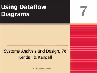
f = ac + bc f 1 edge a b c f 0 0 0 0 0 0 1 0 0 1 0 0 0 1 1 1 1 0 0 0 1 0 1 1 1 1 0 0 1 1 1 1 0 edge a b b c c c c 0 0 0 0 0 1 1 1 Truth table Decision tree BDD Construction – naïve way • Ordered BDD
f a b b c c c c 0 0 0 0 0 1 1 1 Binary Decision Diagrams (BDD) • Based on recursive Shannon expansion f = a fa+ a’ fa’ • Compact data structure for Boolean logic • can represents sets of objects (states) encoded as Boolean functions • Canonical representation • reduced ordered BDDs (ROBDD) are canonical • essential for verification
Theorem Theorem 1 (Bryant - 1986) ROBDD’s are canonical Thus two functions are the sameiff their ROBDD’s are equivalent graphs (isomorphic). Of course must use same order for variables.
Onset is Given by all Paths to “1” F = b’+a’c’ = ab’+a’cb’+a’c’BDD encodesall paths to the 1 node Notes: • By tracing paths to the 1 node, we get a cover of pairwise disjoint cubes. • The power of the BDD representation is that it does not explicitly enumerate all paths; rather it represents paths by a graph whose size is measured by the number of the nodes, and not paths. • A DAG can represent an exponential number of paths with a linear size (number of nodes) in terms of its variables. f a 0 1 fa = cb’+c’ c 1 fa= b’ b 0 0 1 0 1
Any reason why Order X1, X2, X3? The lower tree is a different tree and that is going to be a PROBLEM!! 0 0 1 1
Root node a a c+bd b c c+bd b b d*b c+d c d c c b b d d 0 1 0 1 BDD Example Two different orderings, same function. f = ab+a’c+bc’d 1 0
Every path from the root to a leaf visits the variables in the SAME ORDER
If we say we insist on x1, x2, x3 order, now what? • Figure on Left is ok • Figure on right is also ok (different but equivalent). Why? • PROBLEM!! Even though they are equivalent they are not canonical
Some Benefits of BDDs • Check for tautology is trivial. • BDD is a constant 1. • Complementation. • Given a BDD for a function f, the BDD for f’ can be obtained by interchanging the terminal nodes. • Equivalence check. • Two functions f and g are equivalent if their BDDs (under the same variable ordering) are the same.
BDDs: Reduction Rules • Reduction Rules for BDDs. • ReducedOrdered BDDs ROBDD.
We will reduce the Diagrams ROBDDs • Idea #1: Hey lets use Decision Diagrams • Idea #2: Lets impose a global variable ordering • Idea #3: Reduction
Notreduced ! a a c c c b b b c 1 1 0 0 ROBDD Ordered BDD (OBDD): Input variables are ordered - each path from root to sink visits nodes with labels (variables) in the same order. not ordered ordered {a,c,b} • Reduced Ordered BDD (ROBDD) - reduction rules: • if the two children of a node are the same, the node is eliminated: • f = v f + v’ f • if two nodes have isomorphic (identical) graphs, they are replaced by one of them • These two rules make it so that each node represents a distinct logic function.
We will use Reduction Rules: • Rule #1 (simple) keep one copy of each constant leaf! • So the result is we got rid of all the redundancy of the leaf nodes. • But can we do better? We still have one X1 node, two X2 nodes, four X3 nodes!!
X Z Y
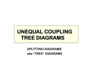
X1 X2 X2 X3 X3 1 0
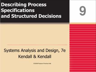
f f1 f2 a a a h g h g b c b c BDD Reduction Rule -2 • Merge duplicate nodes (isomorphic subgraphs) • Nodes must be unique f1 = fa’ g(b) + fa h(c) = f2 f = f1 = f2
f a g g b b BDD Reduction Rules -3 • Eliminate redundant nodes (with both edges pointing to same node) f = a g(b) + a’ g(b) = g(b)
f f a a a b b b b b c c c c c c c 0 0 0 1 1 1 BDD Construction – Example f = (a+b)c • 2. Merge duplicate nodes 3. Remove redundant nodes 1. Merge terminal nodes
We started with a Decision Diagram which is big We reduced it and have now ROBDD RESULT: ROBDD is a Canonical Form (data structure) for any Boolean Function! Great property to have, the simplest form of a graph is a canonical form
Reduced Binary Decision Diagrams … v1 is the root; index(v1)=1 meaning that v1 is related to first variable in the order i.e. x1=a
BDDs: Sharing • Sharing in BDDs. • Advantages of Sharing.
f x F points to 0 0 1 0 f F points to 1 1 • So far we showed how to construct a Reduced Ordered BDD • What can we do with it? Represent any Boolean Function • We can Share nodes in BDDs
x1xor x2xor x3xor x4 X1X4 + X2X4 Make X1=1, X2=1, X3=1, X4=0 will lead to a 1
x3xor x4 G = x2x4 x3xnor x4 x4‘
The big grey boxes of S3 and Cout are the same shared function (identical) Question: Do we have to build the grey stuff twice?? (BDD for S3 and BDD for Cout) The Answer should be NO since it is inefficient
S Cout shared
BDDs: Applications • How are BDDs really implemented? • Applications: • Are two complicated logic circuits equivalent? • If not, how are they different? • How you can make a complicated Boolean function equal 1. • How can ordering help?
H H G F H We cannot implement and build BDDs flat! Not practical. Is there a better way? Always start with reduced ordered BDDs We use recursive methods (DIVIDE & CONQUER) BDD packages are implemented using different functions.
Simple calls to operators (AND, OR, …) creates the Binary Decision Diagram Incrementally • Can this work for more complicated networks? YES (using BDD Packages) • However, we have to think of “What are we going to do with variable ordering”?
Shared BDDs What values for H which make it “1” F G Remember that Boolean functions represent different pieces of logic. Remember also that ROBDDare canonical . Since we are building shared BDDs they will be exactly the same, you get the same graph. What inputs make functions F, G different? In reality we can connect all variables to inputs of two blocks and the output connected to XOR
a a F = a’bc + abc + ab’c G = ac + bc b b c c 0 0 1 1 Application to Verification • Equivalence Checking of combinational circuits • Canonicity property of BDDs: • if F and G are equivalent, their BDDs are identical (for the same ordering of variables)
f if X1=1, X2=don’t care, X3=don’t care, X4=1 1 If we can prove that the function F points to the 1 node then we can easily say it is a Tautology! How about statisfiability? In example on right hand side: Satisfiability is achieved if X1=1, X2=don’t care, X3=don’t care, X4=1 Or another path would be X1=0, X2=1, X3=don’t care and X4=1 Another operator in BDD package (satisfiability)
H a ab b c 1 0 ab’c Application to SAT • Functional test generation • SAT, Boolean satisfiability analysis • to test for H = 1 (0), find a path in the BDD to terminal 1 (0) • the path, expressed infunction variables, gives a satisfying solution (test vector) • Problem:?? size explosion!!!
F F’ ¬ • Complement ¬ F = F’ • (switch the terminal nodes) F(y) F(x,y) Restrict x=b 1 0 0 0 0 1 1 1 Logic Manipulation using BDDs Useful operators • Complement ¬ F = F’ • (switch the terminal nodes) • Restrict: F|x=b = F(x=b)where b = const • To restrict variable x to 1, reconnect all incoming edges to nodes x to their1-nodes • To restrict variable x to 0, reconnect all incoming edges to nodes x to their0-nodes
a a a d c d d b b b b b b b c c c 0 0 0 0 1 1 1 1 Restrict Operator ( f (c=0, d=1) ) f = (a+d)(b+c)+a’d’bc fc’d= (a+1)b = b fc’ = (a+d)b fc’d = b Original BDD • Set c = 0 • Set d = 1 Restricted BDD
A op B a a b c c d d 0 1 0 1 Apply Operation • Concept • Basic technique for building OBDD from Boolean formula. A op B | Result • OBDD representing composite function • AopB Arguments A, B, op • A and B: Boolean Functions • Represented as OBDDs • op: Boolean Operation (e.g., ^, &, |)
The APPLY Operation This is the most important of all the operations that can be performed on the BDDs. • The APPLY operation provides the basic method for creating the representation of a function according to the operators in a Boolean expression or logic gate network. • APPLYtakes graphs representing functions f1 and f2 , a binary operator <op> and produces a reduced graph representing the function f1 <op> f2 defined as : [f1 <op> f2 ] ( x1, x2, … , xn ) = f1(x1, x2, … , xn ) <op> f2 (x1, x2, … , xn ) • The algorithm proceeds from the roots of the 2 argument graphs downward, creating vertices in the result graph at the branching points of the 2 argument graphs. • The control structure of the algorithm is based on the Shannon’s expansion equation/theorem given below: f1 <op> f2 = ~xi . ( f1|xi= 0 <op> f2 |xi = 0 ) + xi . ( f1|xi= 1 <op> f2 |xi = 1 )
The ITE Operator • This is based on the Shannon’s expansion theorem and this is called the ‘If-Then-Else’operator. This is a ternary operator defined as follows: ITE( F, G, H ) = F.G + ~F.H where F, G , H are 3 arbitrary switching functions. • A very important property of the ITE operator which is of great interest for this presentation, and for BDD in general, is that all two-argument operators can be expressed in terms of theITE operator . • The above mentioned property gives great power to manipulate switching functions and hence are used extensively in manipulating the BDD.