Combinational Logic Implementation
This text discusses the implementation of combinational logic using two-level logic, NAND and NOR gates, and the conversion between different logic forms. It covers topics such as gate delays, hazards, regular logic, multiplexers, decoders, PAL/PLAs, and ROMs.

Combinational Logic Implementation
E N D
Presentation Transcript
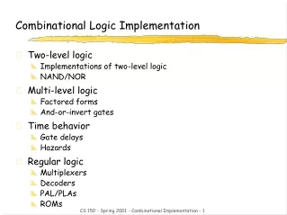
Combinational Logic Implementation • Two-level logic • Implementations of two-level logic • NAND/NOR • Multi-level logic • Factored forms • And-or-invert gates • Time behavior • Gate delays • Hazards • Regular logic • Multiplexers • Decoders • PAL/PLAs • ROMs CS 150 - Spring 2001 - Combinational Implementation - 1
Implementations of Two-level Logic • Sum-of-products • AND gates to form product terms(minterms) • OR gate to form sum • Product-of-sums • OR gates to form sum terms(maxterms) • AND gates to form product CS 150 - Spring 2001 - Combinational Implementation - 2
Two-level Logic using NAND Gates • Replace minterm AND gates with NAND gates • Place compensating inversion at inputs of OR gate CS 150 - Spring 2001 - Combinational Implementation - 3
Two-level Logic using NAND Gates (cont’d) • OR gate with inverted inputs is a NAND gate • de Morgan's: A' + B' = (A • B)' • Two-level NAND-NAND network • Inverted inputs are not counted • In a typical circuit, inversion is done once and signal distributed CS 150 - Spring 2001 - Combinational Implementation - 4
Two-level Logic using NOR Gates • Replace maxterm OR gates with NOR gates • Place compensating inversion at inputs of AND gate CS 150 - Spring 2001 - Combinational Implementation - 5
Two-level Logic using NOR Gates (cont’d) • AND gate with inverted inputs is a NOR gate • de Morgan's: A' • B' = (A + B)' • Two-level NOR-NOR network • Inverted inputs are not counted • In a typical circuit, inversion is done once and signal distributed CS 150 - Spring 2001 - Combinational Implementation - 6
Two-level Logic using NAND and NOR Gates • NAND-NAND and NOR-NOR networks • de Morgan's law: (A + B)' = A' • B' (A • B)' = A' + B' • written differently: A + B = (A' • B')’ (A • B) = (A' + B')' • In other words –– • OR is the same as NAND with complemented inputs • AND is the same as NOR with complemented inputs • NAND is the same as OR with complemented inputs • NOR is the same as AND with complemented inputs AND OR AND OR NOR NAND NOR NAND CS 150 - Spring 2001 - Combinational Implementation - 7
A A NAND B B Z Z NAND C C NAND D D Conversion Between Forms • Convert from networks of ANDs and ORs to networks of NANDs and NORs • Introduce appropriate inversions ("bubbles") • Each introduced "bubble" must be matched by a corresponding "bubble" • Conservation of inversions • Do not alter logic function • Example: AND/OR to NAND/NAND CS 150 - Spring 2001 - Combinational Implementation - 8
A A NAND B B Z Z NAND C C NAND D D Conversion Between Forms (cont’d) • Example: verify equivalence of two forms Z = [ (A • B)' • (C • D)' ]' = [ (A' + B') • (C' + D') ]' = [ (A' + B')' + (C' + D')' ] = (A • B) + (C • D) ü CS 150 - Spring 2001 - Combinational Implementation - 9
A B Z C D \A A NOR NOR \B B Z NOR Z C \C NOR NOR D \D Conversion Between Forms (cont’d) • Example: map AND/OR network to NOR/NOR network Step 1 Step 2 conserve "bubbles" conserve "bubbles" CS 150 - Spring 2001 - Combinational Implementation - 10
A B Z C D \A NOR \B NOR Z \C NOR \D Conversion Between Forms (cont’d) • Example: verify equivalence of two forms Z = { [ (A' + B')' + (C' + D')' ]' }' = { (A' + B') • (C' + D') }' = (A' + B')' + (C' + D')' = (A • B) + (C • D) ü CS 150 - Spring 2001 - Combinational Implementation - 11
Multi-level Logic • x = A D F + A E F + B D F + B E F + C D F + C E F + G • Reduced sum-of-products form – already simplified • 6 x 3-input AND gates + 1 x 7-input OR gate (may not exist!) • 25 wires (19 literals plus 6 internal wires) • x = (A + B + C) (D + E) F + G • Factored form – not written as two-level S-o-P • 1 x 3-input OR gate, 2 x 2-input OR gates, 1 x 3-input AND gate • 10 wires (7 literals plus 3 internal wires) A BC DEFG X CS 150 - Spring 2001 - Combinational Implementation - 12
C D Level 1 Level 2 Level 3 Level 4 F B A original AND-OR network B \C C D introduction and conservation of bubbles F B A B \C C D F \B A redrawn in terms of conventional NAND gates B \C Conversion of Multi-level Logic to NAND Gates • F = A (B + C D) + B C' CS 150 - Spring 2001 - Combinational Implementation - 13
C D F Level 1 Level 2 Level 3 Level 4 B A B original AND-OR network \C C D F B A introduction and conservation of bubbles B \C \C \D F B redrawn in terms of conventional NOR gates \A \B C Conversion of Multi-level Logic to NORs • F = A (B + C D) + B C' CS 150 - Spring 2001 - Combinational Implementation - 14
A A (a) (b) B B F F C C X X D D add double bubbles at inputs original circuit A A X (c) B F (d) C \X B F \D C \X \D distribute bubbles some mismatches insert inverters to fix mismatches Conversion Between Forms • Example CS 150 - Spring 2001 - Combinational Implementation - 15
possible implementation logical concept A A B B Z Z C C D D Invert AND NAND NAND OR Invert & & 2x2 AOI gate symbol 3x2 AOI gate symbol + + & & AND-OR-Invert Gates • AOI function: three stages of logic—AND, OR, Invert • Multiple gates "packaged" as a single circuit block CS 150 - Spring 2001 - Combinational Implementation - 16
& A A' + 0 1 1 0 & B' F A B B Conversion to AOI Forms • General procedure to place in AOI form • Compute complement of the function in sum-of-products form • By grouping the 0s in the Karnaugh map • Example: XOR implementation––A xor B = A' B + A B' • AOI form: F = (A' B' + A B)' CS 150 - Spring 2001 - Combinational Implementation - 17
A 0 1 0 0 1 1 1 0 C B Examples of using AOI gates • Example: • F = B C' + A C' + A B • F' = A' B' + A' C + B' C • Implemented by 2-input 3-stack AOI gate • F = (A + B) (A + C') (B + C') • F' = (B' + C) (A' + C) (A' + B') • Implemented by 2-input 3-stack OAI gate • Example: 4-bit equality function • Z = (A0B0+A0'B0')(A1B1+A1'B1')(A2B2+A2'B2')(A3B3+A3'B3') each implemented in a single 2x2 AOI gate CS 150 - Spring 2001 - Combinational Implementation - 18
A0 B0 & + & A1 B1 & + & NOR Z A2 B2 & + & A3 B3 & + & Examples of Using AOI Gates (cont’d) • Example: AOI implementation of 4-bit equality function high if A0 B0low if A0 = B0 conservation of bubbles if all inputs are low then Ai = Bi, i=0,...,3 output Z is high CS 150 - Spring 2001 - Combinational Implementation - 19
Summary for Multi-level Logic • Advantages • Circuits may be smaller • Gates have smaller fan-in • Circuits may be faster • Disadvantages • More difficult to design • Tools for optimization are not as good as for two-level • Analysis is more complex CS 150 - Spring 2001 - Combinational Implementation - 20
Time Behavior of Combinational Networks • Waveforms • Visualization of values carried on signal wires over time • Useful in explaining sequences of events (changes in value) • Simulation tools are used to create these waveforms • Input to the simulator includes gates and their connections • Input stimulus, that is, input signal waveforms • Some terms • Gate delay—time for change at input to cause change at output • Min delay–typical/nominal delay–max delay • Careful designers design for the worst case • Rise time—time for output to transition from low to high voltage • Fall time—time for output to transition from high to low voltage • Pulse width—time an output stays high or low between changes CS 150 - Spring 2001 - Combinational Implementation - 21
A B C D F Momentary Changes in Outputs • Can be useful—pulse shaping circuits • Can be a problem—incorrect circuitoperation (glitches/hazards) • Example: pulse shaping circuit • A' • A = 0 • delays matterin function D remains high for three gate delays after A changes from low to high F is not always 0 pulse 3 gate-delays wide CS 150 - Spring 2001 - Combinational Implementation - 22
+ resistor A B open switch C D Oscillatory Behavior • Another pulse shaping circuit close switch initially undefined open switch CS 150 - Spring 2001 - Combinational Implementation - 23
Hazards/Glitches • Hazards/glitches: unwanted switching at the outputs • Occur when different paths through circuit have different propagation delays • As in pulse shaping circuits we just analyzed • Dangerous if logic causes an action while output is unstable • May need to guarantee absence of glitches • Usual solutions • 1) Wait until signals are stable (by using a clock): preferable (easiest to design when there is a clock – synchronous design) • 2) Design hazard-free circuits: sometimes necessary (clock not used – asynchronous design) CS 150 - Spring 2001 - Combinational Implementation - 24
1 1 0 1 0 0 1 1 0 0 1 1 0 0 Types of Hazards • Static 1-hazard • Input change causes output to go from 1 to 0 to 1 • Static 0-hazard • INput change causes output to go from 0 to 1 to 0 • Dynamic hazards • Input change causes a double changefrom 0 to 1 to 0 to 1 OR from 1 to 0 to 1 to 0 CS 150 - Spring 2001 - Combinational Implementation - 25
A S B S' Static Hazards • Due to a literal and its complement momentarily taking on the same value • Thru different paths with different delays and reconverging • May cause an output that should have stayed at the same value to momentarily take on the wrong value • Example: A B F S S' F hazard static-0 hazard static-1 hazard CS 150 - Spring 2001 - Combinational Implementation - 26
A F 3 2 B 1 C Dynamic Hazards • Due to the same versions of a literal taking on opposite values • Thru different paths with different delays and reconverging • May cause an output that was to change value to change 3 times instead of once • Example: A C B1 B2 B3 F hazard dynamic hazards CS 150 - Spring 2001 - Combinational Implementation - 27
Making Connections • Direct point-to-point connections between gates • Wires we've seen so far • Route one of many inputs to a single output --- multiplexer • Route a single input to one of many outputs --- demultiplexer control control multiplexer demultiplexer 4x4 switch CS 150 - Spring 2001 - Combinational Implementation - 28
A Y Z B A Y Z B Mux and Demux • Switch implementation of multiplexers and demultiplexers • Can be composed to make arbitrary size switching networks • Used to implement multiple-source/multiple-destination interconnections CS 150 - Spring 2001 - Combinational Implementation - 29
Mux and Demux (cont'd) • Uses of multiplexers/demultiplexers in multi-point connections A0 A1 B0 B1 Sa Sb multiple input sources MUX MUX A B Sum multiple output destinations Ss DEMUX S0 S1 CS 150 - Spring 2001 - Combinational Implementation - 30
I1 I0 A Z0 0 0 00 0 1 00 1 0 10 1 1 01 0 0 01 0 1 11 1 0 11 1 1 1I1 I0 A Z0 0 0 00 0 1 00 1 0 10 1 1 01 0 0 01 0 1 11 1 0 11 1 1 1 A Z0 I01 I1 Multiplexers/Selectors • Multiplexers/Selectors: general concept • 2n data inputs, n control inputs (called "selects"), 1 output • Used to connect 2n points to a single point • Control signal pattern forms binary index of input connected to output Z = A' I0 + A I1 functional form logical form two alternative forms for a 2:1 Mux truth table CS 150 - Spring 2001 - Combinational Implementation - 31
I0I1I2I3I4I5I6I7 8:1mux Z I0I1I2I3 4:1mux Z I0I1 2:1mux Z A A B A B C Multiplexers/Selectors (cont'd) • 2:1 mux: Z = A' I0 + A I1 • 4:1 mux: Z = A' B' I0 + A' B I1 + A B' I2 + A B I3 • 8:1 mux: Z = A'B'C'I0 + A'B'CI1 + A'BC'I2 + A'BCI3 + AB'C'I4 + AB'CI5 + ABC'I6 + ABCI7 • In general, Z = (mkIk) • in minterm shorthand form for a 2n:1 Mux n 2 -1 k=0 CS 150 - Spring 2001 - Combinational Implementation - 32
Gate Level Implementation of Muxes • 2:1 mux • 4:1 mux CS 150 - Spring 2001 - Combinational Implementation - 33
I0I1I2I3 8:1mux 4:1mux Z 2:1mux I4I5I6I7 I0I1 8:1mux 2:1mux 4:1mux I2I3 2:1mux 4:1mux Z B C A I4I5 2:1mux I6I7 2:1mux A B C Cascading Multiplexers • Large multiplexers implemented by cascading smaller ones alternativeimplementation control signals B and C simultaneously choose one of I0, I1, I2, I3 and one of I4, I5, I6, I7control signal A chooses which of theupper or lower mux's output to gate to Z CS 150 - Spring 2001 - Combinational Implementation - 34
10100011 01234567 F 8:1 MUX S2 S1 S0 A B C Multiplexers as General-purpose Logic • 2n:1 multiplexer implements any function of n variables • With the variables used as control inputs and • Data inputs tied to 0 or 1 • In essence, a lookup table • Example: • F(A,B,C) = m0 + m2 + m6 + m7 = A'B'C' + A'BC' + ABC' + ABC = A'B'(C') + A'B(C') + AB'(0) + AB(1) CS 150 - Spring 2001 - Combinational Implementation - 35
10100011 01234567 A B C F0 0 0 10 0 1 00 1 0 10 1 1 01 0 0 01 0 1 01 1 0 11 1 1 1 C'C'01 C'C'01 0123 F 4:1 MUX 8:1 MUX S1 S0 A B S2 S1 S0 A B C Multiplexers as General-purpose Logic (cont’d) • 2n-1:1 mux can implement any function of n variables • With n-1 variables used as control inputs and • Data inputs tied to the last variable or its complement • Example: • F(A,B,C) = m0 + m2 + m6 + m7 = A'B'C' + A'BC' + ABC' + ABC = A'B'(C') + A'B(C') + AB'(0) + AB(1) F CS 150 - Spring 2001 - Combinational Implementation - 36
1D01D’DD’D’ 01234567 A 1 1 0 0 1 0 1 0 8:1 MUX D 0 1 1 0 1 1 0 1 S2 S1 S0 C B A B C Multiplexers as General-purpose Logic (cont’d) • Generalization • Example: F(A,B,C,D) implemented by an 8:1 MUX I0 I1 . . . In-1 In F. . . . 0 0 011. . . . 1 0 101 0 In In' 1 four possible configurationsof truth table rows can be expressedas a function of In • n-1 mux control variables • single mux data variable choose A,B,C as control variablesmultiplexer implementation CS 150 - Spring 2001 - Combinational Implementation - 37
Demultiplexers/Decoders • Decoders/demultiplexers: general concept • Single data input, n control inputs, 2n outputs • Control inputs (called “selects” (S)) represent binary index of output to which the input is connected • Data input usually called “enable” (G) 1:2 Decoder: O0 = G S’ O1 = G S 3:8 Decoder: O0 = G S2’ S1’ S0’ O1 = G S2’ S1’ S0 O2 = G S2’ S1 S0’ O3 = G S2’ S1 S0 O4 = G S2 S1’ S0’ O5 = G S2 S1’ S0 O6 = G S2 S1 S0’ O7 = G S2 S1 S0 2:4 Decoder: O0 = G S1’ S0’ O1 = G S1’ S0 O2 = G S1 S0’ O3 = G S1 S0 CS 150 - Spring 2001 - Combinational Implementation - 38
G \G O0 O0 S S O1 O1 G \G O0 O0 O1 O1 O2 O2 O3 O3 S1 S1 S0 S0 Gate Level iImplementation of Demultiplexers • 1:2 Decoders • 2:4 Decoders active-high enable active-low enable active-high enable active-low enable CS 150 - Spring 2001 - Combinational Implementation - 39
01234567 A'B'C'A'B'CA'BC'A'BCAB'C'AB'CABC'ABC “1” 3:8 DEC S2 S1 S0 A B C Demultiplexers as General-purpose Logic • n:2n decoder implements any function of n variables • With the variables used as control inputs • Enable inputs tied to 1 and • Appropriate minterms summed to form the function demultiplexer generates appropriate minterm based on control signals (it "decodes" control signals) CS 150 - Spring 2001 - Combinational Implementation - 40
0 A'B'C'D'1 A'B'C'D2 A'B'CD'3 A'B'CD4 A'BC'D'5 A'BC'D6 A'BCD'7 A'BCD8 AB'C'D'9 AB'C'D10 AB'CD'11 AB'CD12 ABC'D'13 ABC'D14 ABCD'15 ABCD0 A'B'C'D'1 A'B'C'D2 A'B'CD'3 A'B'CD4 A'BC'D'5 A'BC'D6 A'BCD'7 A'BCD8 AB'C'D'9 AB'C'D10 AB'CD'11 AB'CD12 ABC'D'13 ABC'D14 ABCD'15 ABCD F1 4:16DEC Enable F2 F3 A B C D Demultiplexers as General-purpose Logic (cont’d) • F1 = A' B C' D + A' B' C D + A B C D • F2 = A B C' D’ + A B C • F3 = (A' + B' + C' + D') CS 150 - Spring 2001 - Combinational Implementation - 41
Cascading Decoders • 5:32 decoder • 1x2:4 decoder • 4x3:8 decoders 0 A'B'C'D'E'1234567 012 A'BC'DE'34567 3:8 DEC 3:8 DEC S2 S1 S0 S2 S1 S0 0123 2:4 DEC F S1 S0 01234567 ABCDE 0 AB'C'D'E'1234567 AB'CDE A B 3:8 DEC 3:8 DEC S2 S1 S0 S2 S1 S0 C D C D E E CS 150 - Spring 2001 - Combinational Implementation - 42
• • • inputs ORarray ANDarray productterms outputs • • • Programmable Logic Arrays • Pre-fabricated building block of many AND/OR gates • Actually NOR or NAND • ”Personalized" by making or breaking connections among gates • Programmable array block diagram for sum of products form CS 150 - Spring 2001 - Combinational Implementation - 43
product inputs outputs term A B C F0 F1 F2 F3AB 1 1 – 0 1 1 0B'C – 0 1 0 0 0 1AC' 1 – 0 0 1 0 0B'C' – 0 0 1 0 1 0A 1 – – 1 0 0 1 reuse of terms Enabling Concept • Shared product terms among outputs F0 = A + B' C' F1 = A C' + A B F2 = B' C' + A B F3 = B' C + A example: input side: personality matrix 1 = uncomplemented in term 0 = complemented in term – = does not participate output side: 1 = term connected to output 0 = no connection to output CS 150 - Spring 2001 - Combinational Implementation - 44
Before Programming • All possible connections available before "programming" • In reality, all AND and OR gates are NANDs CS 150 - Spring 2001 - Combinational Implementation - 45
B C A AB B'C AC' B'C' A F0 F1 F2 F3 After Programming • Unwanted connections are "blown" • Fuse (normally connected, break unwanted ones) • aAnti-fuse (normally disconnected, make wanted connections) CS 150 - Spring 2001 - Combinational Implementation - 46
A B C D AB A'B' CD' C'D AB+A'B' CD'+C'D Alternate Representation for High Fan-in Structures • Short-hand notation--don't have to draw all the wires • Signifies a connection is present and perpendicular signal is an input to gate notation for implementing F0 = A B + A' B' F1 = C D' + C' D CS 150 - Spring 2001 - Combinational Implementation - 47
A B C A'B'C' A'B'C A'BC' A'BC AB'C' AB'C ABC' ABC A B C F1 F2 F3 F4 F5 F6 0 0 0 0 0 1 1 0 0 0 0 1 0 1 0 1 1 1 0 1 0 0 1 0 1 1 1 0 1 1 0 1 0 1 0 0 1 0 0 0 1 0 1 1 1 1 0 1 0 1 0 1 0 0 1 1 0 0 1 0 1 0 0 1 1 1 1 1 0 0 1 1 F1 F2 F3 F4 F5 F6 Programmable Logic Array Example • Multiple functions of A, B, C • F1 = A B C • F2 = A + B + C • F3 = A' B' C' • F4 = A' + B' + C' • F5 = A xor B xor C • F6 = A xnor B xnor C full decoder as for memory address bits stored in memory CS 150 - Spring 2001 - Combinational Implementation - 48
PALs and PLAs • Programmable logic array (PLA) • What we've seen so far • Unconstrained fully-general AND and OR arrays • Programmable array logic (PAL) • Constrained topology of the OR array • Innovation by Monolithic Memories • Faster and smaller OR plane a given column of the OR array has access to only a subset of the possible product terms CS 150 - Spring 2001 - Combinational Implementation - 49
A A A A 0 0 X 1 1 0 X 0 0 1 X X 1 0 X X 0 1 X 0 0 1 X 0 0 0 X X 0 0 X X 0 0 X 1 0 1 X 1 0 1 X X 0 1 X X 0 1 X 0 0 1 X 0 1 1 X X 1 1 X X D D D D C C C C A B C D W X Y Z0 0 0 0 0 0 0 00 0 0 1 0 0 0 10 0 1 0 0 0 1 10 0 1 1 0 0 1 00 1 0 0 0 1 1 00 1 0 1 1 1 1 00 1 1 0 1 0 1 00 1 1 1 1 0 1 11 0 0 0 1 0 0 11 0 0 1 1 0 0 01 0 1 – – – – –1 1 – – – – – – B B B B PALs and PLAs: Design Example • BCD to Gray code converter K-map for W K-map for X minimized functions: W = A + B D + B C X = B C' Y = B + C Z = A'B'C'D + B C D + A D' + B' C D' K-map for Y K-map for Z CS 150 - Spring 2001 - Combinational Implementation - 50