
Background
E N D
Presentation Transcript
Background • Who does this project addresses to? • Handicapped. • Amputated limbs. • Paralyzed. • Motivation Statistics
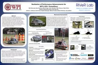
Project’s Goals The objective of this project is to drive a robotic arm and vehicle wirelessly by moving certain muscles in the body. An important attribute of this system is a correct sample of electrical signals from muscles (EMG) and the translation of these signals into an action.
Demonstration Link
Design Stages • Create interface between radio transmitter and microcontroller. • Control the robotic arm & vehicle by microcontroller. • Design and build Amplifying and Filtering circuit. • Sample the EMG signal and translate it to movement commands.
The EMG Signal • An EMG signal is a small electrical current that is released when a muscle is contracted. • The EMG signal can be read or measured by placing conductive elements or electrodes on skin surface. • The voltage level of the signal is 0.01-10mV at freq range of 0-500Hz
Filter & Amplifier Circuit • Uses Instrumentation Amplifier and Universal Active Filter. • Amplifies the low measured signal to make it suitable for a sample. • Filters Background noise.
Micro Controller - Pic18 • A/D-Sample a analog signal that already been filtered and amplified. • The resolution- 10 bit, 4.88mV/bit. • Create interface to radio transmitter • PWM signal. Long Sync Pulse 5v Ch 1 Ch 2 Ch 3 Ch 4 Ch 5 0v Sync Pulse Sync Pulse Sync Pulse Sync Pulse Sync Pulse Sync Pulse
Micro Controller - Pic18 EMG Signal
Communication System • Laser 4 Remote control • Receives the signal from microcontroller. • Modulates and transmit 72MHz FM modulated signal. • The Hitec HFD-08RO receiver • Located on the mobile vehicle • Demodulates the FM Signal • Parsers the received data to 8 channel
Robotic Arm &Vehicle • The robotic arm is based on Hi-Tech servo motors. • The angel of the motor is determined by the width of the PWM it gets. • The robotic arm controlled by 5 PWM channels (have 5 motors). • 4X4 weal drive vehicle controlled by 2 PWM channels.
Digital Camera & Monitor • The camera is tracking the movement of the robot and sending a PAL video signal at 2.4GHz. • The monitor has an internal video receiver with LCD screen and Video and Audio outputs.
Future research • Working a circuit board (will reduce noise ). • Reducing size of communication system. • Working in frequency domain with DSP processor . • Reduce energy consumption. • Integrate EEG-electric signals from the brain.