Download
1 / 16
180 likes | 391 Views
Time resolved diagnostics for pulsed magnetron plasmas. N. N. S. S. Magnetrons. Chamber. Gases Mixtures of Ar, O 2 , N 2 etc. Substrates Glass, polymers, metals etc. Target Metallic and semi-conducting. S. N. Magnetron Variable magnetic field. Pulsed DC Power supply

E N D
Time resolved diagnostics for pulsed magnetron plasmas Technological Plasmas Research Group
N N S S Magnetrons Chamber Gases Mixtures of Ar, O2 , N2 etc Substrates Glass, polymers, metals etc Target Metallic and semi-conducting S N Magnetron Variable magnetic field Pulsed DC Power supply Frequencies 0 – 350 kHz Technological Plasmas Research Group
Analysis techniques • Probes: • Electrical: Langmuir, double, triple, emissive • Energy: Thermal • Magnetic field: B-dot • Optical emission spectroscopy • Film characteristics: Structure, topography, composition • Optical imaging • Energy resolved mass spectroscopy Technological Plasmas Research Group
Window Chamber Filters Substrate ICCD Camera Target Magnetron P C Oscilloscope Delay generator Power supply Optical imaging Purpose: To observe the effect of the driving voltage waveform on the spatial and temporal distribution of emission from plasma • ICCD camera fitted with a zoom lens • Observe different species by the use of filters • Short exposure times (50 ns) • Sweep exposure window through pulse cycle • Record temporal and spatial evolution Technological Plasmas Research Group
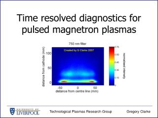
Filters • Several optical filters were employed. • Optical emission spectroscopy performed to identify the spectral lines within the bandwidth of each filter. • Filter with a central wavelength of 750 nm, chosen so as to observe two transitions in argon neutrals. Technological Plasmas Research Group
Sample image Substrate Cathode The red box represents the temporal location when the data recorded Technological Plasmas Research Group
Movie: Raw data Technological Plasmas Research Group
Optical imaging: Abel inversion Technique: Data collected along ‘line of sight’ can be used to produce radial profiles cathode y where, E(r) = emissivity of the plasma I (y) = line integrated intensity R = radius of the plasma y = displacement of the intensity profile r = radial distance from the axis of symmetry r Central axis R Plasma • Standard two dimensional images can be processed to produce radial profiles that are perpendicular to the line of sight Technological Plasmas Research Group
Movie: Abel inverted data Technological Plasmas Research Group
Detached region ‘Cold’ electron density Emissivity 1016 m-3 0.25 1.6 0.20 1.2 0.15 Normalised emissivity (arb units) Axial distance z (mm) 0.8 0.10 0.4 0.05 0.0 0.00 Electron density plots courtesy of Dr. Alena Vetushka Technological Plasmas Research Group
target chamber central axis of chamber mass spectrometer magnetron substrate Energy resolved mass spectroscopy Purpose: To observe the effect of the driving voltage waveform on the ion energy distribution functions (IEDF’s) of argon ions arriving at the substrate • Energy resolved mass analyser modified to enable time resolved measurements • Argon ion energy distribution functions recorded throughout the duration of the pulse cycle • Exposure time of 1 s • Sweep exposure window through pulse cycle Technological Plasmas Research Group
Movie: IEDF 1 Data recorded using: 1 s steps between successive data sets Technological Plasmas Research Group
Movie: IEDF 2 Data recorded using: 100 ns steps between successive data sets Technological Plasmas Research Group
Method of production ? Time dependent variation in plasma potential assessed via emissive probe Technological Plasmas Research Group
Conclusions • Imaging • Yield information on the structure of the discharge • The presence of different electron energy groups • Time and energy resolved mass spectroscopy • Record the temporal variation in the energy of ions arriving at the substrate • Results suggest methods of production Results are in agreement with those suggested by other techniques Technological Plasmas Research Group
Acknowledgements • EPSRC • Dr Alena Vetushka (probe measurements) • Dr Paul Bryant (Abel inversion) • Prof Nick Braithwaite • Mr Alan Roby Technological Plasmas Research Group