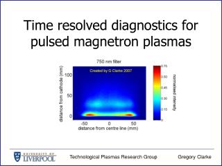
Download
1 / 28
290 likes | 565 Views
Physics and technology of high-voltage pulsed plasmas. Bob Merlino Plasma Physics Seminar April 5, 2010. outline. Controlled thermonuclear fusion Early work (1950’s) Stellarators at PPPL Linear (Z) pinch Toroidal pinch Magnetic mirrors High voltage linear q pinch

E N D
Physics and technology of high-voltage pulsed plasmas Bob Merlino Plasma Physics Seminar April 5, 2010
outline • Controlled thermonuclear fusion • Early work (1950’s) • Stellarators at PPPL • Linear (Z) pinch • Toroidal pinch • Magnetic mirrors • High voltage linear q pinch • Implosion or shock heating • Pulsed power technology • HV toroidal q pinch
reaction rate (cm3/s) ion temperature (keV) controlled thermonuclear fusion D + T (3.5 MeV) + n (14.1 MeV) • heating • confinement • Lawson criterionfor ignition:nt> 1014 cm3 s - n is the plasma density - tis the confinement time
2 i 1 minor cross section early work in magnetic fusion • Project Matterhorn begun in 1951 at Princeton University as a classified project • Problem with toroidal devices is that magnetic field is non-uniform (stronger on inner radius than outer radius) ultimately this leads to plasma moving outward • loss of confinement “pump-out” • First experiments at PPPL studied confinement in Stellarators – toroidal magnetic field with rotational transform i
Lyman Spitzer, Jr. CONFIDENTIAL: Such material would cause damageor be prejudicial to national security if publicly available. - US Atomic Energy Commission – AEC - US Energy Research and Development Administration (ERDA) - US Department of Energy (DOE) 1977
Model A Figure 8 Stellarator 1954 Spitzer invited Van Allen to come to Princeton in 1953-54 to initiate an experimental program. It was Van Allen’s idea to start with a table-top device to demonstrate the Stellarator concept.
HV capacitor bank JxB Plasma heating in a linear (Z) pinch • Pass a large current through a gas making a linear discharge • JxB force causes pinching • Current heats the plasma • if dI/dt large enough, plasmas with keV temperatures can be formed • how fast? dI/dt ~ 1013 A/s • Since V = L dI/dt, very high voltages and low inductances are required • Problem is that linear pinch is unstable to sausage and kink instabilities
ZETA - toroidal pinchAtomic Energy ResearchEstablishment, Harwell, UK Toroidal pinches • Even if the linear pinch were stable, it could never be a viable fusion device because the electrodes introduce impurities that would cause the plasma to radiate away a large fraction of its energy • Must consider closed magnetic configurations with no internal electrodes • Zeta in UK • Perhapsotron at Los Alamos • These are “stabilized” pinches due to presence of toroidal magnetic field
Other Plasma heating devices • work at Los Alamos. the Naval Research Lab in DC and the Univ. MD concentrated on methods of producing hot plasmas in linear q pinch devices • groups at Oak Ridge National Lab and Lawrence Livermore National Lab investigated heating and confinement in magnetic mirrors
pinches • simple straight solenoidal magnetic field line devices • magnetohydrodynamically stable • produce very hot plasmas Ti ~10 keV • very high efficiency for conversion of electrical energy into plasma energy • inherently a pulsed device • confinement limited by plasma squirting out the ends
Maryland High Voltage q Pinch one-turn solenoidal coil pre-ionized plasma Pyrex or quartz vacuum vessel Main capacitor bank • solenoid coil was 1m long by 46 cm id • plasma formed in H2 or D2 at P ~ few mtorr • preionization done by discharging capacitor ringing at 150 kHz • initial plasma “fully ionized” at n ~ 1013 cm3 with +/- 400 G bias field • main bank: 250 kV, dI/dt rises in < 10 nsec giving dB/dt ~ 1010 G/s
pinch physics Bo BMain induced current in plasma sheath radially inwardJ x B force • plasmas are diamagnetic, so • currents are induced on the surface • the J x Bforce makes plasma implode, causing it to be heated – shock or implosion heating snowplow model • to exclude field penetration • plasma resistivity allows magnetic field to penetrate
pulsed power technology • how do you produce voltage pulses of hundreds of kA with currents of hundreds of kA in fractions of microseconds? • there are no commercially available devices that can provide this • pulsed power technology developed in US and UK (R. A. Fitch) for Radar in WW II • in US, main development program was at Sandia National Lab
3 mm polyethylene pinch HV technology oil 2500 g H2O + CuSO4
output switch L O A D inversion switch (spark gap) crowbar switch with crowbar I DC with out crowbar t Marx generatorcharge capacitors in parallel then switch to series to get voltage multiplication Marx output voltage = N x # capacitors
Magnetic field diagnostics B 4 mm
B Main implosion field antiparallel to initial bias field 0 Main implosion field parallel to initial bias field Magnetic field profiles
20 cm 0 -20 cm -70 cm 0 +70 cm Reconnection and tearing in q pinch reversed or antiparallel field configuration t = 440 ns J. H. Irby, J. F. Drake, and H. R. Griem, Phys. Rev. Lett.42, 228 (1979)
confinement in pinch • limited by end loss • e.g., L = 1 m, Te = 1 keV, tconf ~ L/Cs,Cs = 2x10⁵ m/s tconf ~ 5 ms • suppose density was ~ 1016 cm-3, how long would a pinch have to be to satisfyn tconf > 1014 cm-3 s ? tconf = 0.01 s L ~ 2 km • LANL tried plugging the ends with solid plugs of quartz or lithium-deuteride
HV generator in transformer oil tank with water + CuSO4 MD High Voltage Toroidal q pinch • goal was to study implosion heating in a toroidal device • determine if Te Ti when fast electron endlosses were eliminated • compliment to SCYLLAC at LANL
HV pulsers: swinging LC generators • Charge capacitors in series • use inductors and switches across every other capacitor module to reverse polarity • gives voltage multiplication • use 6 generators connected to toroidal coil with parallel-plate transmission lines • Total energy: 600 kJ* • output voltage: 580 kV • output current: 3 MA in < 1 ms • dI/dt = 6.0 x 10¹² A/s • built by Maxwell Labs * 3400 lbs moving at 65 mph
Coil current Neutron emission soft x-ray emissionthick Al filter soft x-ray emissionthin Al filter time (ms) Neutron and x-ray emission
Magnetic field profiles in toroidal q pinch Antiparallel Parallel
toroidal q pinch: conclusions • Electrons attain higher temperatures as compared with linear q pinch, now Te Ti • Implosion, shock or turbulent heating processes remain effective in toroidal geometry • However, attempts to achieve MHD equilibrium through the use of vertical fields and toroidal currents failed • Plasma abruptly drifts to outer wall after implosion phase