Download
1 / 3
30 likes | 138 Views
This document presents a novel method for testing high-speed VLSI chips (0.5-1GHz) with slower Automatic Test Equipment (ATE) operating at 100-200MHz. Due to the high cost of replacing existing ATE, this method allows for testing without adding extra hardware to the chip. By utilizing a strategy where low-speed tests are repeated multiple times based on the speed ratios, this approach achieves similar path coverage to at-speed testing. This method is essential for ensuring functional path testing while adapting to the advancing speed of VLSI technology.

E N D
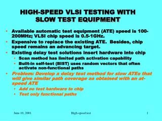
HIGH-SPEED VLSI TESTING WITH SLOW TEST EQUIPMENT • Available automatic test equipment (ATE) speed is 100-200MHz; VLSI chip speed is 0.5-1GHz. • Expensive to replace the existing ATE. Besides, chip speed remains an advancing target. • Existing delay test solutions insert hardware into chip • Scan method has limited path activation capability • Built-in self-test (BIST) uses random vectors that often activate non-functional paths • Problem: Develop a delay test method for slow ATEs that will give similar path coverage as obtained with an at-speed ATE • Add no test hardware to chip • Test only functional paths June 10, 2001 High-speed test 1
A NEW METHOD • Given a vector-set with specific at-speed PDF coverage, the ATE repeats the slow-speed test N times, where N is the ratio of chip-speed to the ATE-speed. • In each slow-speed vector application • Flip-flops are clocked at the rated high-speed • Output monitoring instant is advanced by an additional interval that equals rated high-speed clock period • Test application time = N 2 x (test time of at-speed ATE) Slow vector application, N=4 Slow output monitoring repeated N times PI Sequential circuit under test (gates and flip-flops) PO Appln. 1 Vector i i+1 CK Appln. 2 Appln. 3 Rated-clock generated by pin-multiplexing Appln. 4 June 10, 2001 High-speed test 2
N=1 (at-speed) N=2 (Half-speed) N=4 (1/4 speed) 4.367 MHz 3.937 MHz* 3.922 MHz* SOME RESULTS OF NEW METHOD 1. Simulated Benchmark circuits (ISCAS’89) S510 : 5,000 random vectors S5378 : 5,000 random vectors 50 At-speed ATE Slow ATE 40 Slow ATE (N=2, 3, 4) gives the same path coverage as at-speed ATE (N=1). 30 Path delay fault Coverage (%) 20 10 1 2 3 4 ATE slowdown factor (N) 2. A 4MHz off-the-shelf chip tested on Agilent 82000 ATE * Some tested paths are longer than those tested by at-speed test. June 10, 2001 High-sped test 3