HIGH SPEED LANYARD RELEASE TEST FIXTURE
430 likes | 673 Views
HIGH SPEED LANYARD RELEASE TEST FIXTURE. Michael Amos, Project Manager Mechanical Engineer Aaron Brechko Mechanical Engineer Joshua Carmer Electrical Engineer. Dr. Benjamin Varela, Faculty Mentor Mechanical Engineer Justin Grigonis Industrial & Systems Engineer Lindsay LaRocca

HIGH SPEED LANYARD RELEASE TEST FIXTURE
E N D
Presentation Transcript
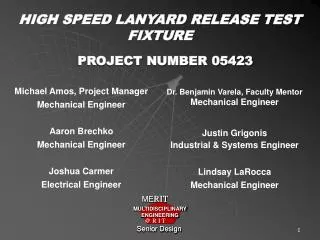
HIGH SPEED LANYARD RELEASE TEST FIXTURE Michael Amos, Project Manager Mechanical Engineer Aaron Brechko Mechanical Engineer Joshua Carmer Electrical Engineer Dr. Benjamin Varela, Faculty Mentor Mechanical Engineer Justin Grigonis Industrial & Systems Engineer Lindsay LaRocca Mechanical Engineer PROJECT NUMBER 05423
Overview • Project Overview • The Process • Desired Outcomes • Key Requirements • Major Design Challenges • Conclusions
Amphenol Aerospace Operations (AAO) “Accepted leader in providing quality connectors… to the Industrial, Military, and Aerospace markets” www.Amphenol-Aerospace.com Sidney, New York
Project Overview • Mission Statement • To design a drive system, with supporting documentation, for an actuation method to test the separation of AAO’s lanyard release connectors. • Executive Summary • What • Why
Lanyard-Release Connector Assembly • Main Components • Lanyard • Operating Sleeve • Plug Shell • Receptacle • Main electrical interface between aircraft and its stores
The Process • Needs Assessment • Concept Development • Many concepts • Feasibility Assessment • Several Concepts • Preliminary Design Review • One design concept
Desired Outcomes / Requirements For AAO’s Selected Concept: • Complete bill of materials • Component and assembly drawings • Provide detailed analysis of fabricated components • Meet new Military Specification MIL-DTL-38999/31D • High speed separation of connector • 30 ft/s ± 10% • Variable Test Velocity • Reliable • Repeatable • Economical • Low-Cycle Time • Safe
Major Design Challenges • Motor Selection • Torque vs. RPM • AC Performance Characteristics • Overall System Dynamics • Component Selection • Clutch/Brake • Controls
Major Components • Motor • 7.5 HP, 3 Phase AC Induction 230 V SmartMotor • Sprockets (6) • Driver • 5.123” diameter, 24 teeth (1) • Driven: • 9.911” diameter, 48 teeth (5) • Chain • Size 50, 5/8” pitch • Two-Single Strands for Upper System (US) • One-Single Strand to connect motor shaft to US
Major Components – Cont’d • Mounting Block • Linear Bearing - Track
Component Selection Process • Choose Motor • Choose Sprockets • Determine force and velocity at mounting block • Re-iterate
Requirements: 30 ft/s 200 lb pull force on lanyard Configuration • At Motor - Driver: • 1400 RPM • At Upper System – Driven: • 700 RPM
Overall System Calculations • Acceleration: a=167.97 ft/s2 t=0.1786 s d=2.68 feet a3 feet • Deceleration: a=-434.64 ft/s2 t=0.069 s d=1.035 feet
Drive Motor Baldor 7.5 HP, 3 Phase Induction SmartMotor • SmartMotor: Integrated Control Board Saves: • $$$ & Man Hours • Programmable Velocity Profiles • Accuracy = 2.9% • Breakdown Torque: • 69.9 ft lbs
Baldor Keypad • Remote control (up to 100 ft) • Indicator lights • Clear LCD Display • Simple • Programmable
Clutch and Brake Component • Enclosed Uni-Module model 215 • One On / One Off Design • 230 VAC Powers up either clutch or brake at any given time • CBC-150-2 Controller
Switch Locations 4. Home 2. Past Test Position 3. Reverse Switch (user activated) 1. At Speed (1400 rpm) Signal From Motor
Control Components • Switches • Emergency Stop • Track • Rocker
Emergency Stop Switch • DPST NO/NC switch • Efficient for control system • Necessary in event of failure of lanyard to disengage
Track Switch • Tells control system the location of the carriage • Makes control system logic simple • SPST maintained contact • Requires ramped contact surface on bottom of carriage
Rocker Switch • Manually switched after each test • Functions as second input needed to control the clutch/brake • Necessary due to limited motor controller outputs • Simple and inexpensive solution
Control Logic / Power Application • Four Switches • Signals Feed Clutch / Brake Decision Logic based on state of each switch • Logic output control feeds gate of Power Switching Transistor to pass 230VAC to power up either Clutch or Brake • Emergency Stop Button included as Safety Measure
Mounting Block Description • Shall Provide • Power transmission between chain and lanyard • Mounting surface for lanyard • Mounting surface for additional components • Should be light weight and rigid
Mounting Block Final Design • 6061 aluminum • Connector mounting surface is perpendicular to plane of motion • 0.25 in fillets on edges to reduce stress concentration • Weight 5 lb (excess material removed) • Mounting points for carriage, chain, and receptacle
Linear Bearing – Track • Provide supporting surface for mounting block movement • Light weight • Withstand acceleration and velocity of the test
Linear Bearing Final Design • INA LFL 32 Linear Bearing • Carriage Weight - 3.5 lbs • Able to withstand nearly 5g’s acceleration
Chain and Sprocket Enclosures • Protect outside environment if failure occurs • Keep drive system components clean • Help prevent human contact • Allow air flow to cool the motor • Allow for easy access for routine services
Chain and Sprocket Enclosures Final Design • 13 ga. sheet metal • 13 ga. expanded sheet metal on sides • Maintenance / Access door to motor • Removable panels for full system service
Provides mounting locations 2” X 2” X 0.125” 6061 Aluminum Welded construction Length determined using basic kinematic equations 192” L x 36” H x 30” D Chain System Frame
Purpose: Support upper chains Mounted via aluminum right angle brackets Polyethylene U-Channel
Ergonomic Analysis • Test Table Height and Width • 95th percentile male / 5th percentile female • Motor access accomplished via side door in test machine frame • Noise • Ear plugs may be necessary
Safety Considerations • Track/sprocket/chain enclosures • Prevent entanglement • Mesh covering over the motor • Allows heat to dissipate • Shock absorbers • Prevents carriage contact with sprockets
Conclusions • MEETS and EXCEEDS Requirements • Velocity (38 ft/s MAX) • Impulsive Pull force (334 lbs MAX) • Strong, Durable and Accurate (2.9%) • Easily Maintained • Variable Velocity Profiles • Mechanical Components Totally Enclosed • $9,000 Total Component Cost
Baldor Induction SmartMotor - Accuracy • MIL-DTL-38999 allows 30 ft/sec 10% (3 ft/sec) • Accuracy = 20 RPM (provided by factory representative)