8255 Programmable Peripheral Interface
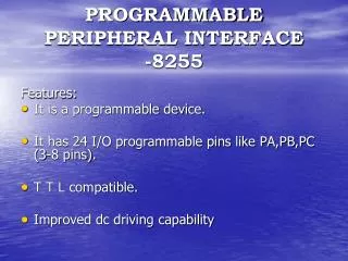
8255 Programmable Peripheral Interface. The Intel 8255 Programmable Peripheral Interface chip is used to give the microprocessor (8088) access to programmable input/ output devices.

8255 Programmable Peripheral Interface
E N D
Presentation Transcript
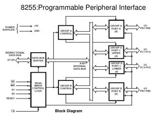
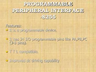
8255 Programmable Peripheral Interface The Intel 8255 Programmable Peripheral Interface chip is used to give the microprocessor (8088) access to programmable input/ output devices. It has three ports for input/ output devices and a control port that contains the control word which programs the 8255 (setting the ports status [I/O] and their modes.
Data bus D[7:0] PA[7:0] A0 8088 PB[7:0] A1 Control port RD WR PC[7:0] RESET CS A7 A6 A5 A4 A3 A2 IO/M 8255 Programmable Peripheral Interface Port A [it could be input or output] PortB[it could be input or output] 8255 Port C [it could be input or output] Control word is sent to the Control Port Two Address lines to select the port [PA, PB, PC, Control port] they could be any two address lines from A7 – A0 RD: Read from port(s) WR: write to port(s) RESET: reset 8255 Chip Select To enable the 8255 according to the Base Address selected Decoding circuit Click here for more
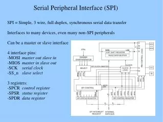
A7 A6 A5 A4 A3 A2 IO/M 8255 Programmable Peripheral Interface • The decoding circuit will enable the 8255 chip • 6 address lines will be inputted to a NAND gate along with IO/M (input output device/Memory) • The remaining 2 address lines will be inputted to the 8255 to select the port [Port A, port B, port C or control port] Example 1 [base address] Assume A7 – A2 are inputted to decoding circuit and A1 - A0 are inputted to 8255 directly to select the port Base Address
A7 A6 A5 A4 A2 A0 IO/M 8255 Programmable Peripheral Interface Example 2 [base address] Assume A7, A6, A5, A4, A2 and A0 are inputted to the same previous decoding circuit and A3 and A1 are inputted to 8255 directly to select the port Base Address