Download
1 / 39
410 likes | 620 Views
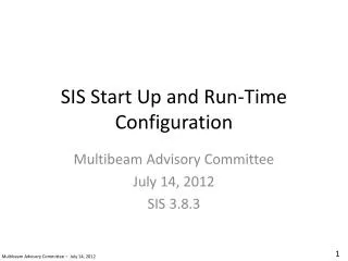
SIS Start Up and Run-Time Configuration. Multibeam Advisory Committee July 14, 2012 SIS 3.8.3. 1. Multibeam Advisory Committee – July 14, 2012. Overview. Start up, New survey Verify installation parameters Set default run-time configuration Additional settings Saving your settings. 2.

E N D
SIS Start Up and Run-Time Configuration Multibeam Advisory Committee July 14, 2012 SIS 3.8.3 1 Multibeam Advisory Committee – July 14, 2012
Overview • Start up, New survey • Verify installation parameters • Set default run-time configuration • Additional settings • Saving your settings 2 Multibeam Advisory Committee – July 14, 2012
Start up, New survey • Start the sounder deck box (TRU), the workstation (HWS) and software (SIS) • Create a new survey project • Verify that all sensor data streams are being received 3 Multibeam Advisory Committee – July 14, 2012
Start up Start SIS. If the sounder deck unit has just been powered up, you may have to wait a few minutes before you can connect to the sounder. You can periodically click the “Rescan” button to attempt to establish communications with the TRU. 4 Multibeam Advisory Committee – July 14, 2012
Start up Once the deck unit (TRU) is responsive, you can select the sounder from this drop down list. 5 Multibeam Advisory Committee – July 14, 2012
Start up Create a new survey project through the following menus: View->Tear Off->New survey 6 Multibeam Advisory Committee – July 14, 2012
Start up Enter the survey project name. Many institutions have naming protocols. If you have none, the following format is recommended: CRUISEID_INSTRUMENT_SEQUENCE_SURVEYNAME The CRUISEID allows for easy sorting of cruises. The INSTRUMENT field helps keep data sorted by instrument. The SEQUENCE field helps keep cruise sub-projects sorted in the order that they were acquired. The SURVEYNAME helps keep track of the purpose of the survey. Here are some examples: FK003_EM710_000_PatchTest FK003_EM710_001_TransitToArea FK003_EM710_002_MainSurvey FK003_EM710_003_ReturnTransit 7 Multibeam Advisory Committee – July 14, 2012
Start up Choose an appropriate grid cell size. For area surveys, choose a value that is close to the resolution of the sounder, typically 1-2% of water depth. This enables real-time data quality assessment since problems with the data will show up in the grid. If you’re collecting data while in transit, it is recommended to choose a coarser grid cell size, otherwise it is our experience that SIS will become unstable after a few days. 8 Multibeam Advisory Committee – July 14, 2012
Start up Go back to the “Basic Parameters” tab and click “Save new survey” then close the “New survey” tear-off window. 9 Multibeam Advisory Committee – July 14, 2012
Start up Your new survey name will be automatically loaded and will populate the survey drop down menu. You may wish to consider creating all the new survey projects anticipated to happen during a cruise in order to ensure/enforce any naming conventions. You can choose from any survey from the drop down box later when you arrive to a particular site so there is no harm in creating the survey project templates in advance. Start the sonar pinging by clicking the “Not Pinging” button. 10 Multibeam Advisory Committee – July 14, 2012
Start up The sonar is now pinging. Verify that all supporting sensors are reporting. Position Surface sound speed Orientation The sonar may not necessarily be able to track the bottom yet. We will take care of that later in this procedure. 11 Multibeam Advisory Committee – July 14, 2012
Verify Installation Parameters • If sensors are not reporting, confirm communication protocols in SIS • Verify sensor linear and angular offsets • Perform Built-In Self Test (BIST) 12 Multibeam Advisory Committee – July 14, 2012
Start up Access the sensor installation parameters through the following menus: View->Tear Off->Installation Parameters. To access some of the functionality, you’ll need to stop the sonar from pinging though there is no harm in examining the installation parameters while the sonar is pinging. 13 Multibeam Advisory Committee – July 14, 2012
Start up Verify the sensor locations against the documented positions. If your vessel has not documented this information, it is good practice to do so. This allows any operator can quickly restore the system to a known good configuration after a system crash/restore, etc. You can verify these while the system is pinging. If you need to change them, the system must not be pinging. 14 Multibeam Advisory Committee – July 14, 2012
Start up Verify the sensor angular offsets against the documented offsets. If your vessel has not documented this information, it is good practice to do so. This allows any operator can quickly restore the system to a known good configuration after a system crash/restore, etc. You can verify these while the system is pinging. If you need to change them, the system must not be pinging. 15 Multibeam Advisory Committee – July 14, 2012 Multibeam Advisory Committee – July 14, 2012
Start up Run the system Built-In Self Tests (BIST). Some tests can be done dockside, this allows for hardware replacement in case of failure. Dockside noise test results should be disregarded as these are often very pessimistic due to the noisy environment typical of ports. Noise tests can be done on site at survey speed to get a better feeling for the noise levels. Having noise measurements under these conditions allows for long-term monitoring of the ship’s acoustic noise environment. The same can be said of the impedance measurements. 16 Multibeam Advisory Committee – July 14, 2012
Start up Save the BIST output once the tests are complete. 17 Multibeam Advisory Committee – July 14, 2012
Start up When saving the BIST output, choose the standard directory used by SIS. This allows other operators to quickly find these files. Follow your institution’s file naming convention, establish one if it doesn’t exist. A good file naming convention allows for ease of analysis of long term trends in system performance, for example, changes in transducer impedance or ship noise levels. 18 Multibeam Advisory Committee – July 14, 2012
Set Default Run-time Configuration • Get the sounder pinging • Configure sounder run-time parameters 19 Multibeam Advisory Committee – July 14, 2012
Start up Start the sounder pinging by clicking the “Not Pinging” button. If any of the warning lamps are red, the sounder may not be able to ping. To help the sonar track the bottom, access the sonar’s run-time parameters through the following menus: View->Tear Off->Runtime parameters. 20 Multibeam Advisory Committee – July 14, 2012
It is also helpful to configure an appropriate depth mode. This controls the pulse length, among other things. Deeper modes use longer pulse lengths to ensure a strong bottom return and to increase the likelihood of detection. AUTO mode will eventually find an appropriate depth mode but it may take longer to track the bottom. If you’re in a hurry, setting an appropriate mode manually will speed the process (see next page). Once the system has found the bottom, you should set the ping mode back to AUTO. This will allow the sounder to automatically adjust the mode depending on water depth. If the system is continually having trouble tracking the seafloor while surveying, you might find it helpful to force an appropriate depth mode. Start up You can inform the sonar of the expected depth (force depth) and limit the depth range in order to help it track the bottom. Once it has found the bottom, it is recommended make the min depth something close to the surface and make the max depth much deeper than the expected depth so as not to accidentally filter the data. 21 Multibeam Advisory Committee – July 14, 2012
You can limit the sounding sector of interest with the angle and coverage fields. The “Max. Coverage” values will vary with sounder model. Safe default settings that won’t clip your data are listed below (these do not indicate potential achievable coverage, they’re just safely bigger than coverage so that we never accidentally clip data): EM710: 3000 m is a safe default EM302: 9000 m is a safe default EM122: 30000 m is a safe default Start up Choose “HIDENS EQDIST” for beam spacing mode to collect the maximum number of soundings across the swath. Setting the “Angular Coverage Mode” to AUTO will allow the sounder to adjust the angular sector in response to what it can reasonably track, e.g. it will reduce the sector if it finds that it cannot track at large angles, this allows for an increased ping rate. You can force the sounder to attempt to track over a larger sector by setting this into MANUAL mode. Your ping rate will drop and you will not gain additional data if the system cannot detect the bottom at the outer edge of the swath. 23 Multibeam Advisory Committee – July 14, 2012
Start up Turn “Pitch stabilization” on. Turn “Yaw stabilization” on with “REL. MEAN HEADING” Mode. If you are synchronizing the sounder with other acoustic instrumentation, be sure to click the “External Trigger” checkbox. Otherwise, make sure it is unchecked since the sounder will not ping until it receives an external transmit trigger. Multibeam Advisory Committee – July 14, 2012
Start up Load a sound speed profile by clicking this button to launch a file browser. The sound speed at the transducer is used for beamforming and beam steering. It is a very critical measurement. If you have a surface velocimeter, then you should always choose SENSOR as the source of sound speed at the transducer. This is the optimal method of compensating for surface sound speed variations. If you do not have such a sensor (or if it is malfunctioning), you can compute the sound speed from a thermosalinograph and then choose “MANUAL” and enter the value in the “Sound Speed” field. If you don’t have access to a thermosalinograph, you can choose “PROFILE” as the source. This will lookup the transducer sound speed from the currently loaded sound speed profile. These last two modes are suboptimal: the manual method requires continual manual updating, the profile method is only good if the profile is up-to-date. You should strive to have a working surface velocimeter along with a spare. 25 Multibeam Advisory Committee – July 14, 2012
Start up Choose the most recent sound speed profile. The sound speed profile is not terribly important if you’re just testing the sounder to make sure everything is working. If you’re about to start a survey, then you should have just measured a sound speed profile and you should choose that file for upload. 26 Multibeam Advisory Committee – July 14, 2012
Start up Once you have chosen a profile, the filename field will turn yellow to indicate that you have made a change that has not been applied yet. Apply the sounds speed profile by clicking the “Use Sound Speed Profile” button. 27 Multibeam Advisory Committee – July 14, 2012
The “Absorption Coefficient” controls the real-time normalization of the seabed imagery. Only choose the “CTD” option if you are uploading SVP profiles with temperature and salinity data in them (the MAC SVP Editor does this when delivering profiles over the network). If you aren’t then choosing “Salinity” is the next best method. Using the mean ocean salinity is a better practice then updating this field with the surface salinity value. This value is best left alone once entered since any changes will lead to changes in seabed imagery signal level and can create headaches in post-processing. Start up You can set various bathymetric filters. You should read the manual to understand what each of these do (too much detail to get into here). Cruise scientists may have thoughts on which filters they’d like to apply; you should provide them with the manual. The settings recommended in the manual should be safe for default values. The “Sector Tracking” filter normalizes the seabed imagery (backscatter) in real-time in an irrecoverable manner. If backscatter is of primary interest, then this should be disabled. 28 Multibeam Advisory Committee – July 14, 2012
Start up You should read the manual to decide if you should apply real-time Data Cleaning. Having “None” is the safest option. 29 Multibeam Advisory Committee – July 14, 2012
Start up If the science party will be correcting for heave residuals in post-processing then you will need to log the appropriate file type. Most deep water work does not benefit much from post-processing of heave since the artifacts are so small compared to the sounding uncertainties at great depth. 30 Multibeam Advisory Committee – July 14, 2012
Additional Settings • Automatic file incrementing interval 31 Multibeam Advisory Committee – July 14, 2012
Start up Access a menu of additional parameters through the following menus: Tools->Custom…->Set parameters. 32 Multibeam Advisory Committee – July 14, 2012
Start up You can set the line increment interval here. This sets how often the system will create a new data file. This is likely going to be a setting that will vary from scientist to scientist and thus is one of the few settings in here that you may need to change on a cruise by cruise basis. Note that you will have to restart SIS for this setting change to take effect. There are numerous additional settings that can be modified in these menus. Familiarize yourself with them when you first begin operating the system. As your experience with the sounder system increases, you should revisit these once in a while as your understanding of what each setting does will increase with time and you will be able to make more informed decisions. 33 Multibeam Advisory Committee – July 14, 2012
Saving Your Settings • Save all of your Installation and Runtime settings for backup and for easy reload 34 Multibeam Advisory Committee – July 14, 2012
Save your installation and run-time parameters by accessing the following menu: File->Export PU parameters… 35 Multibeam Advisory Committee – July 14, 2012
SIS has a recommended default location for configuration files. You should use this as it will ease the task of loading pre-set parameters with different operators. You should also back these files up on another computer and take great care to make sure they are not modified. 36 Multibeam Advisory Committee – July 14, 2012
Choose a filename that is sensible and easy for others to understand. Having the date in the filename is useful for keeping track of setting history. Using YYYYMMDD as the file prefix allows for easier setting management since the files will be ordered in time when sorted by name in file browser windows. If you’re curious, you can examine the contents of the file (open in Wordpad due to line-ending confusion in Notepad). Be VERY careful not to modify it. Modifying the text file to change settings is NOT RECOMMENDED!!! 37 Multibeam Advisory Committee – July 14, 2012
Add a meaningful comment when prompted. This helps with setting history management. If you had a particular reason to change the default settings, this is a good place to document it. You can reload these system settings in the future by accessing the following menus: File->Import PU parameters. YOU WILL NEED TO RESTART SIS AFTER IMPORT. It is good practice to spend time deciding on reasonable default settings and then saving them such that any operator can quickly bring the system to a safe default state. 38 Multibeam Advisory Committee – July 14, 2012
Questions? Feedback? Suggestions? • Please email us: • mac-help@unols.org 39 Multibeam Advisory Committee – July 14, 2012