### Designing Embedded Systems: Integrating Hardware and Software for Flexibility and Efficiency ###
This guide provides a comprehensive overview of the basic design processes involved in embedded systems, focusing on integrating hardware and software solutions. It outlines essential steps including requirement gathering, specification writing, design, implementation, testing, and maintenance. Key concepts such as analog/digital inputs, outputs, and VHDL architecture for components like half-adders are also discussed. The document explores various software process models, including prescriptive, agile, and evolutionary models, detailing their advantages and disadvantages to aid in selecting the right approach for different projects. ###

### Designing Embedded Systems: Integrating Hardware and Software for Flexibility and Efficiency ###
E N D
Presentation Transcript
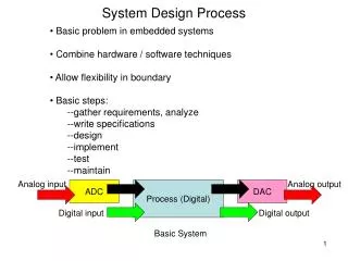
System Design Process • Basic problem in embedded systems • Combine hardware / software techniques • Allow flexibility in boundary • Basic steps: • --gather requirements, analyze • --write specifications • --design • --implement • --test • --maintain Analog input Analog output ADC Process (Digital) DAC Digital input Digital output Basic System
Hardware Design Space Issues: --timing --synch/asynch --parallelism --digital/analog --space --power
--VHDL ARCHITECTURE (BEHAVIORAL/DATAFLOW): architecture PROCESS_BEHAVIOR of HALF ADDER is begin SUM_PROC: process(A,B) begin if (A = B) then S <= '0' after 5 ns; else S<= (A or B) after 5 ns; end if; end process SUM_PROC; CAR_PROC: process (A,B) begin case A is when '0' => COUT <= A after 5 ns; when '1' => COUT <= B after 5 ns; when others => COUT <= 'X' after 5 ns; end case; end process CAR_PROC; end PROCESS_BEHAVIOR; --VHDL entity entity HALFADDER is port (A,B: in bit; S,COUT: out bit); end ADDER; --VHDL ARCHITECTURE (BEHAVIORAL) architecture CONCURRENT of HALF ADDER is --this is a behavioral description ("delay" = 5 ns here) --it does NOT imply that XOR or AND gates will be used in the implementation begin S <= (A xor B) after 5 ns; COUT <= (A and B) after 5 ns; end CONCURRENT; LIBRARY COMPONENT (PHYS. / BEHAV./ STRUCT.) Example (half adder, based on Figure 4, Chapter 13, Handbook of Mechatronics and additions) TRANSISTOR (PHYSICAL) NETLIST (STRUCTURAL) n1: a b o1 n2: a c o2 n3: o1 o2 o3 Analog component: --VHDL ARCHITECTURE (STRUCTURAL) architecture A of HALFADDER is component XOR port (X1,X2: in bit; O: out bit); end component; component AND port (X1,X2: in bit; O: out bit); end component; begin G1: XOR port map (A,B,S); G2: AND port map (A,B,COUT); end A;
Software Process Model Software Process Model: --A development strategy that encompasses the process, methods, and tools --Specific model is chosen based upon the project/application, the methods/tools to be used, resources available, and the deliverables required basic model: problemdevelopintegrate each step is carried out recursively until an appropriate level of detail is achieved
Process Model Types Software Process Model Types: “Prescriptive” Model includes a specific set of tasks, along with a workflow for these tasks and definite milestones and outcomes for each task; end result is the desired product "Agile" Model tends to be simpler than prescriptive models; emphasis is on incremental development, customer satisfaction, and minimal process overhead "Mathematical" Formal Method Model stresses mathematical rigor and formal proofs that product is meeting carefully-defined goals
Analysis Design Code Test Maintain Waterfall Model Linear Sequential Model (“waterfall model”): Sequential approach from system level through analysis, design, coding, testing, support--oldest and most widely used paradigm Advantages: --better than nothing --can be appropriate for for small, well-understood projects Disadvantages: --Real projects rarely follow a sequential flow --Requirements usually not fully known. --Working version not available until late in project.
Some Common Prescriptive Models Some common prescriptive models used in practice: "Basic": Linear Sequential Model Prototyping Model RAD Model "Evolutionary" (product evolves over time): Incremental Model Spiral Model Concurrent Development Model Component-Based Development
Prototyping Model Prototyping Model: customer defines set of general objectives; no details on input, processing, output requirements; may be unsure of algorithm efficiency, adaptability, OS, human/machine issues Advantages: --Focuses on what is visible to customer --Quick design leads to a prototype --Prototype evaluated by the customer who can refine requirements --Ideal mechanism for identifying and refining SW requirements Disadvantages: --Customer sees something that appears to work and wants it. --Less than ideal choices move from prototype to product SW Prototyping: A-->D-->C-->T-->M (A=analysis, D=design, C=coding, T=testing, M=maintenance)
Rapid Application Development Model RAD Model: Rapid Application Development: incremental model, emphasizes short development cycle. component based: requirements fully understood and scope constrained: good for information systems applications. Advantages: Assumes "4th Gen" techniques: reuse existing programs or create reusable components. Only new components need to be tested. Disadvantages: Enough human resources to create the right number of RAD teams; system must be modularizable; high risk, i.e., new technologies. RAD: A-->D1 D2-->C-->T Integrate-->T-->M D2-->C-->T Reuse-->C-->T (A=analysis, D=design, C=coding, T=testing, M=maintenance)
Incremental Model Incremental Model: Elements of linear sequential (applied repetitively) with prototyping. As result of use, a plan is developed for next increment. Advantages: Unlike prototyping, an operational product is delivered at each increment. Disadvantages: Variable staffing at each increment (task dependent). Risk analysis must be done at each increment. Incremental: A-->D-->C-->T-->M-->A-->D-->C-->T--> ……-->M (A=analysis, D=design, C=coding, T=testing, M=maintenance)
Spiral Model Spiral Model:couples iterative nature of protoyping with the controlled and systematic aspect of the linear model. Potential for rapid development of incremental versions of SW. 1 spiral might be a paper model next a prototype then beta….etc. Advantages: Realistic approach to large-scale systems. Developer/customer understand risk at each stage. Disadvantages: Requires risk assessment expertise; relies on it for success. • Spiral: T<--C<--D<--A T--- >M • A-->D C • A-->D • (A=analysis, D=design, C=coding, T=testing, M=maintenance)
Concurrent Development Model Concurrent Development Model:represented schematically as a series of major technical activities, tasks and their associated states. often used in client/server applications but applicable to all SW development : Advantages: provides an accurate picture of project state. Disadvantages: must be able to decompose project appropriately Concurrent: A-->A1-->D-->C-->T-->Integrate-->T-->M A1-->D-->C-->T A1-->D-->C-->T (A=analysis, D=design, C=coding, T=testing, M=maintenance)
Component Based Development Component Based Development:emphasizes the creation of classes that encapsulate data and the algorithms to manipulate the data. Reusability. Much like spiral model ie evolutionary and iterative. But composes applications from prepackaged SW components (classes) Process steps: --candidate class is identified --library is searched for existing class --if none exists, then one engineered using object-oriented methods. Advantages: Faster development and lower costs. Disadvantages: requires expertise in this type of development • Component based: • A-->D-->Library-->Integrate-->T-->M • C • (A=analysis, D=design, C=coding, T=testing, M=maintenance)
Software Process Models--Comparison Graphical comparison of these process models: • Basic waterfall model: A-->D-->C-->T-->M • (A=analysis, D=design, C=coding, T=testing, M=maintenance) • Prototyping: A-->D-->C-->T-->M • RAD: A-->D1 D2-->C-->T Integrate-->T-->M • D2-->C-->T • Reuse-->C-->T • Incremental: A-->D-->C-->T-->M-->A-->D-->C-->T--> ……-->M • M • Spiral: T<--C<--D<--A TComponent based: • A-->D CA-->D-->Library-->Integrate-->T-->M • A-->D C • Concurrent: A-->A1-->D-->C-->T-->Integrate-->T-->M A1-->D-->C-->T • A1-->D-->C-->T
Formal Methods Formal Methods: formal mathematical specification of SW. Uses rigorous mathematical notation. Advantages: --Ambiguity, incompleteness, inconsistency found more easily. --Serves as a basis for program verification. --”promise” of defect-free SW Disadvantages: --Very time consuming --extensive training required --not a good communication mechanism (especially for customer) --handles syntax well; not so successful with semantics uses: Safety critical SW (medicine and avionics) or when severe economic hardship will be incurred by developer if error occurs
Question: what design methodology encompasses both? One possibility: UML (unified modeling language) • graphical language • supports dynamic behavior • modular, object-based • extensions possible (e.g., AUML, “agent UML”)
UML: stands for "unified modeling language” unifies methods of Booch, Rumbaugh (OMT or Object Modeling Technique), and Jacobson (OOSE or Object-Oriented Software Engineering) mainly a modeling language, not a complete development method Early versions -- second half of the 90's Not all methods we will use are officially part of the UML description UML--definition
Most of the examples below, plus more on UML, issues can be found in: 1. Booch, Rumbaugh, and Jacobson, The Unified Modeling Language User Guide 2. Fowler and Scott, UML Distilled 3. Horstmann, Practical Object-Oriented Development in C++ and Java 4. Pressman, Software Engineering, A Practitioner's Approach UML--references
We will use the following tools: • Analysis and specification: • Use cases • Dataflow diagrams • Analysis, specification, and design: • Entity-relationship (ER) diagrams • Class-Responsibility-Collaborator (CRC) cards • Object message diagrams • State diagrams • Sequence diagrams Tools for analysis, specification, and design
Use cases USE CASES: a part of the ”Unified Modeling Language" (UML) which we will also use for design each identifies a way the system will be used and the "actors" (people or devices) that will use it (an interaction between the user and the system) each use case should capture some user-visible function and achieve some discrete goal for the user an actual user can have many actor roles in these use cases an instance of a use case is usually called a "scenario"
Example use case Example (based on Booch, Rumbaugh, and Jacobson, The Unified Modeling Language User Guide): System boundary
Encounters an error condition Arms/disarms system Responds to alarm event Use case—detailed example (Pressman) • Example: “SAFEHOME” system (Pressman, Software Engineering, p. 161) • Use case: InitiateMonitoring • Primary actor (1) • Goal in context (2) • Preconditions (3) • Trigger (4) • Scenario (5) • Exceptions (6) • Priority (system development) (7) • When available (8) • Frequency of use (9) • Channel to actor (10) • Secondary actors (11) • Channels to secondary actors (12) • Open issues (13) Homeowner Accesses system via internet Sensors System administrator Reconfigures sensors and related system features Pressman, p. 163, Figure 7.3
Example: “SAFEHOME” system Use case:InitiateMonitoring 1. Primary actor: homeowner 2. Goal in context: set the system to monitor sensors when the homeowner leaves the house or remains inside the house 3. Preconditions: system already programmed with homeowner’s password and can recognize the sensors 4. Trigger: homeowner decides to turn on the alarm system
5. Scenario • Homeowner observes control panel • Homeowner enters password • Homeowner selects “stay” or “away” • Homeowner observes that read alarm light has come on, indicating the system is armed
6. Exceptions • Control panel is not ready; homeowner must check all sensors and reset them if necessary • Control panel indicates incorrect password (one beep)—homeowner enters correct password • Password not recognized—must contact monitoring and response subsystem to reprogram password • Stay selected: control panel beeps twice and lights stay light; perimeter sensors are activated • Away selected: control panel beeps three times and lights away light; all sensors are activated
7. Priority: essential, must be implemented 8. When available: first increment 9. Frequency of use: many times per day 10. Channel to actor: control panel interface 11. Secondary actors: support technician, sensors 12. Channels to secondary actors: support technician: phone line sensors: hardwired and wireless interfaces
13. Open issues • Should there be a way to activate the system without the use of a password or with an abbreviated password? • Should the control panel display additional text messages? • How much time does the homeowner have to enter the password from the time the first key is pressed? • Is there a way to deactivate the system before it actually activates? • Use case diagram?
Example: what would be a use case for: vending machine user • Primary actor: • Goal in context: • Preconditions: • Trigger: • Scenario: • Exceptions: • Priority: • (system development): • When available: • Frequency of use: • Channel to actor: • Secondary actors: • Channels to • secondary actors: • Open issues:
System Tests • Note: • Use cases can form a basis for system acceptance tests • For each use case: • Develop one or more system tests to confirm that the use case requirements will be satisfied • Add explicit test values as soon as possible during design phase • These tests are now specifically tied to the use case and will be used as the top level acceptance tests • Also at this stage develop tests for performance and usability requirements (these may be qualitative as well as quantitative)
Data flow diagram (DFD): ----graphical technique to show information flow and transforms applied as data move from input to output ----each function or information transformer is represented by a circle or "bubble" ----data labels are placed on arrows showing information flow ----external entities (data "producers" or "consumers") are shown as square boxes
The data flow diagram does not describe the processing sequence; it is not a flowchart. But it can be very useful during requirements analysis for a system being developed. A DFD can be used to provide a functional model for the system being developed, thus supplementing the class relationship, object message, and state diagram models of UML. Functional models based on DFD's were part of the Object Modeling Technique (OMT) developed by Rumbaugh, one of the three main designers of UML.
Example (based on examples in Pressman, Software Engineering, A Practitioner's Approach): Keyboard CRT Internet Memory Stick Memory Stick
Entity-relationship diagrams / class diagrams: • These diagrams represent the relationships between the classes in the system. These represent a static view of the system. • There are three basic types of relationship: • inheritance ("is-a") • aggregation ("has-a”) • association ("uses") • These are commonly diagrammed as follows: ER diagrams
manager employee ER diagram: is-a is-a: draw an arrow from the derived to the base class:
car tire 1 4 ER diagram--has-a has-a: draw a line with a diamond on the end at the "container" class. Cardinalities may also be shown (1:1, 1:n, 1:0…m; 1:*, i.e., any number > 0, 1:1…*, i.e., any number > 1):
company car gasstation employee ER diagram--uses uses or association: there are many ways to represent this relationship, e.g., employs works for
CRC cards CRC cards: class--responsibilities--collaborators cards "responsibilities" = operators, methods "collaborators" = related classes (for a particular operator or method) Make one actual card for each discovered class, with responsibilities and collaborators on the front, data fields on the back. CRC cards are not really part of UML, but are often used in conjunction with it.
Class Mailbox Operations Relationships (Responsibilities) (Collaborators) get current message Message, Messagequeue play greeting ----------- Example (based on Horstmann, Practical Object-Oriented Development in C++ and Java): front back Class Mailbox Queue of new messages Queue of kept messages Greeting Extension number Passcode
Common types of classes which the developer can look for include: • tangible things, e.g., Mailbox, Document • system interfaces and devices, e.g., DisplayWindow, Input Reader • agents, e.g., Paginator, which computes document page breaks, or InputReader • events and transactions, e.g., MouseEvent,CustomerArrival • users and roles, e.g., Administrator, User • systems, e.g., mailsystem (overall), InitializationSystem (initializes) • containers, e.g., Mailbox, Invoice, Event • foundation classes, e.g., String, Date, Vector, etc. Common classes
Example—bank simulation (Horstmann) Horstmann, Mastering Object-Oriented Design in C++, Wiley, 1995 Teller 1 Teller 2 Customer 3 Customer 2 Customer 1 Teller 3 Teller 4
Bank Statistics Customer Bank Application Arrival Departure EventQueue Event Example—bank simulation (Horstmann), cont. An initial solution (Horstmann, p. 388):
Bank Statistics Customer Bank Simulation Arrival Departure EventQueue Event Example—bank simulation (Horstmann), cont. An improved solution (Horstmann, p. 391):
Bank Statistics Bank Statistics Customer Bank Customer Bank Application Simulation Arrival Arrival Departure Departure EventQueue EventQueue Event Event Comparison What simplifications have been made? Why?