Download
1 / 15
150 likes | 248 Views
Explore domestic wastewater treatment at a secondary facility using the extended aeration sludge process. Learn about the plant's inflow, headworks, secondary treatment, and filtration process.

E N D
Virtual Tour of Municipal Wastewater Treatment Plant (WWTP)Prepared by Dr. Richard O. Mines, Jr., P.E.Mercer UniversityEnvironmental Engineering Department1400 Coleman AvenueMacon, GA 31207
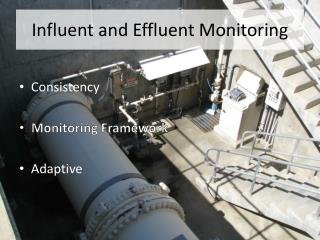
This paper documents the treatment of domestic wastewater at a secondary wastewater treatment facility utilizing the extended aeration sludge process. This 14-MGD facility was completed in 1974 at a cost of $3.3 million. More recently, a 7-MGD expansion along with sludge de-watering facility and a post-aeration pumping station has increased the capacity of this facility to 21 MGD of wastewater. Influent Bar Screens and Pumping Station • Raw wastewater is received at the WWTP through gravity and force mains. Three types of wastewater enter the facility: domestic or municipal wastewater, combined domestic and industry wastewater, and industrial wastewater. The raw wastewater first passes through traveling bridge bar screens that remove large debris, rags, cigarette butts, etc. • Figures 1 and 2 shows the influent bar screens.
After passing through the bar screens, the screened wastewater is pumped up to the headworks, by one of four centrifugal pumps. • Figures 4 and 5 show a centrifugal pump and motor which provides energy to the pump.
HeadworksThe screened wastewater is pumped from the influent pumping station to the headworks. Wastewater flows by gravity from this point through the treatment process. Figures 6, 7, and 8 show the different types of wastewater entering the treatment train. Each of the influent chambers in aerated to mix and aerate the wastewater.
Wastewater flows from each influent chamber through a parshall flume. These flumes are used for measuring the wastewater flowrate. • Figure 9 shows one of the parshall flumes. • After the flow is measured, the wastewater flows through an aerated, concrete, channel to the grit chamber (Figure 10). Figure 10 shows one of the aerated grit chambers. • Figure 11 shows a grit washer used for removing organics from the grit.
A microscreen is used for removing additional materials that were not removed by the bar screens (Figure 12). • Figure 13 shows the materials removed by the microscreen. They are emptied into a dumpster and transported to the landfill for disposal. • Grit from the grit washers • is discharged into a • dumpster and hauled to a • landfill for disposal • (Figure 14).
Secondary Treatment • After preliminary treatment, the wastewater flows into one of three extended aeration basin trains. Secondary treatment consists of aeration followed by secondary clarification. Substrate is used by microorganisms during aeration followed by solids-liquid separation in the secondary clarifiers. Here the wastewater is completely-mixed by mechanical aerators. This provides oxygen from the air to the heterogeneous culture of microorganisms in the wastewater that use it to oxidize the organic mater and to keep the microorganisms in suspension. The microbes also utilize some of the nitrogen and phosphorus in the wastewater in cell synthesis. The typical composition of a microorganism may be represented by the following formula: C60H87O23N12P. The microorganisms use carbon, nitrogen, phosphorus, and oxygen to synthesize new microbial cells that are removed in the secondary clarifiers.
Secondary Treatment (cont.) • Thickened sludge or biomass in the secondary clarifiers is returned to the head of the aeration basin in order to maintain a specified concentration of microorganisms or solids in the aeration basins. The recycled sludge or biomass is called return activated sludge (RAS) and must be pumped back to the head of the aeration basins. The wastewater within the aeration basin is called "mixed liquor". The average unit of time that the biomass or microorganisms remain in the activated sludge process is called "mean cell residence time" or "sludge age" or "solids retention time". Generally, the longer the biomass remains in the system, the better quality effluent that is achieved. To maintain a given "sludge age" in the system, a certain quantity of sludge or biomass must be wasted from the system. At steady-state conditions, the amount of biomass that is wasted from the system is equal to the quantity of biomass or microorganisms that are grown. The sludge that is wasted from the system is called "waste activated sludge" or WAS. Waste sludge is also pumped from the bottom of the secondary clarifiers to the gravity thickeners where it is thickened prior to aerating and dewatering.
Figures 15, 16, 17, and 18 show the aeration basins, mechanical aerators, secondary clarifiers, and secondary clarifier effluent weirs.
Filtration • After secondary clarification, the wastewater flows by gravity to the sand filters that remove additional suspended solids that were not removed during clarification. • Figure 19 shows a picture of the mudwell and Figure 20 is a photo of the sand filters that receives the backwash water. There are a total of eight sand filters in operation at this WWTP.
Chlorination and Chlorine Storage Building • After filtration, the wastewater must be disinfected prior to discharge. Chlorine is added to the wastewater before it enters the chlorine contact chamber where it remains approximately 30 minutes. This allows enough time for the chlorine to kill pathogens in the wastewater. Oxygen is also added to the wastewater through diffusers. The chlorine residual is measured continuously and must be removed from the wastewater before discharging into a river. Chlorine is stored in 2-ton cylinders in an open metal frame building. Chlorinators are used for dissolution of chlorine gas into water prior to injection into the wastewater. • Figure 21 shows the chlorine contact basin. • Figure 22 shows the effluent from the chlorine • contact basin. • Figure 23 is a photo of the blowers used for • providing air for post-aeration.
Figure 24 is the chlorine residual analyzer that continuously monitors the chlorine residual so that the proper dose of sodium bisulfite (Figure 25) can be injected into the wastewater prior to discharge. Normally, the effluent will flow by gravity to the river. During periods when the water level in the river is high, effluent pumps (Figure 26) must be used for pumping the water into the river.
Figure 27 is a photo of the chlorine building and Figure 28 shows the chlorine cylinders. Figure 29 shows one of the chlorinators.
Sludge Treatment and Disposal • Sludge, or biosolids from the secondary clarifiers is wasted to the gravity thickeners (Figure 30). Here the sludge is thickened prior to sending it to the aerated holding tanks (Figure 31). From the aerated holding tanks, the thickened sludge is pumped to the belt filter press (Figure 32). Polymer is added to enhance dewatering of the sludge. The dewatered sludge is loaded onto trucks (Figure 33) and hauled to a processing facility, which composts the sludge, and then land applies it onto agricultural land.
Figures 34, 35, and 36 show different types of sludge composted at the facility.