Pumps and Pumping Stations
340 likes | 821 Views
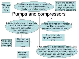
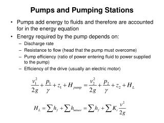
Pumps and Pumping Stations. Pumps add energy to fluids and therefore are accounted for in the energy equation Energy required by the pump depends on: Discharge rate Resistance to flow (head that the pump must overcome)

Pumps and Pumping Stations
E N D
Presentation Transcript
Pumps and Pumping Stations • Pumps add energy to fluids and therefore are accounted for in the energy equation • Energy required by the pump depends on: • Discharge rate • Resistance to flow (head that the pump must overcome) • Pump efficiency (ratio of power entering fluid to power supplied to the pump) • Efficiency of the drive (usually an electric motor)
Static discharge head Static suction head Pump Jargon • (Total) Static head – difference in head between suction and discharge sides of pump in the absence of flow; equals difference in elevation of free surfaces of the fluid source and destination • Static suction head – head on suction side of pump in absence of flow, if pressure at that point is >0 • Static discharge head – head on discharge side of pump in absence of flow Total static head
Static discharge head Static suction lift Pump Jargon • (Total) Static head – difference in head between suction and discharge sides of pump in the absence of flow; equals difference in elevation of free surfaces of the fluid source and destination • Static suction lift – negative head on suction side of pump in absence of flow, if pressure at that point is <0 • Static discharge head – head on discharge side of pump in absence of flow Total static head
Static discharge head Static discharge head Static suction lift Static suction head Pump Jargon Total static head (both) Note: Suction and discharge head/lift measured from pump centerline
Pump Jargon • (Total) Dynamic head, dynamic suction head or lift, and dynamic discharge head – same as corresponding static heads, but for a given pumping scenario; includes frictional and minor headlosses Energy Line Dynamic discharge head Total dynamic head Dynamic suction lift
El = 730 ft Example. Determine the static head, total dynamic head (TDH), and total headloss in the system shown below. ps=6 psig El = 640 ft pd=48 psig El = 630 ft
El = 6349 to 6357 ft 30 to 48 expansion 8500of 36 pipe w/one 90o bend and eight butterfly valves El = 6127 to 6132 ft Short 30 pipe w/30 butterfly valve 4000of 48 pipe w/two 45o bends Example. A booster pumping station is being designed to transport water from an aqueduct to a water supply reservoir, as shown below. The maximum design flow is 25 mgd (38.68 ft3/s). Determine the required TDH, given the following: • H-W ‘C’ values are 120 on suction side and 145 on discharge side • Minor loss coefficients are 0.50 for pipe entrance 0.18 for 45o bend in a 48-in pipe 0.30 for 90o bend in a 36-in pipe 0.16 and 0.35 for 30-in and 36-in butterfly valves, respectively • Minor loss for an expansion is 0.25(v22 v12)/2g
Determine pipeline velocities from v=Q/A.. v30=7.88 ft/s, v36=5.47 ft/s, v48=3.08 ft/s • Minor losses, suction side:
Loss of velocity head at exit: • Total static head under worst-case scenario (lowest water level in aqueduct, highest in reservoir): • Total dynamic head required:
Pump Power • P = Power supplied to the pump from the shaft; also called ‘brake power’ (kW or hp) • Q = Flow (m3/s or ft3/s) • TDH = Total dynamic head • = Specific wt. of fluid (9800 N/m3 or 62.4 lb/ft3 at 20oC) • CF = conversion factor: 1000 W/kW for SI, 550 (ft-lb/s)/hp for US • Ep = pump efficiency, dimensionless; accounts only for pump, not the drive unit (electric motor) Useful conversion: 0.746 kW/hp
2 El = 230 ft 1 10 mi of 48 pipe, e =0.003 ft El = 100 ft Example. Water is pumped 10 miles from a lake at elevation 100 ft to a reservoir at 230 ft. What is the monthly power cost at $0.08/kW-hr, assuming continuous pumping and given the following info: • Diameter D = 48 in; Roughness e = 0.003 ft, Efficiency Pe =80% • Flow = 25 mgd = 38.68 ft3/s • T = 60o F • Ignore minor losses
2 El = 230 ft 1 10 mi of 48 pipe, e =0.0003 ft El = 100 ft Find f from Moody diagram
2 El = 230 ft 1 10 mi of 48 pipe, e =0.0003 ft El = 100 ft
Pump Selection • System curve – indicates TDH required as a function of Q for the given system • For a given static head, TDH depends only on HL, which is approximately proportional to v2/2g • Q is proportion to v, so HL is approximately proportional to Q2 (or Q1.85 if H-W eqn is used to model hf) • System curve is therefore approximately parabolic
40 ft 6 ft Example. Generate the system curve for the pumping scenario shown below. The pump is close enough to the source reservoir that suction pipe friction can be ignored, but valves, fittings, and other sources of minor losses should be considered. On the discharge side, the 1000 ft of 16-in pipe connects the pump to the receiving reservoir. The flow is fully turbulent with D-W friction factor of 0.02. Coefficients for minor losses are shown below.
The sum of the K values for minor losses is 2.52 on the suction side and 5.52 on the discharge side. The total of minor headlosses is therefore 8.04 v2/2g. An additional 1.0 v2/2g of velocity head is lost when the water enters the receiving reservoir. The frictional headloss is: Total headloss is therefore (8.04+1.0+15.0)v2/2g = 24.04 v2/2g. v can be written as Q/A, and A = pD2/ 4 = 1.40 ft2. The static head is 34 ft. So:
System curve Static head
Pump Selection • Pump curve – indicates TDH provided by the pump as a function of Q; • Depends on particular pump; info usually provided by manufacturer • TDH at zero flow is called the ‘shutoff head’ • Pump efficiency • Can be plotted as fcn(Q), along with pump curve, on a single graph • Typically drops fairly rapidly on either side of an optimum; flow at optimum efficiency known as “normal” or “rated” capacity • Ideally, pump should be chosen so that operating point corresponds to nearly peak pump efficiency (‘BEP’, best efficiency point)
Shutoff head Rated hp Rated capacity Pump Performance and Efficiency Curves
Pump Efficiency • Pump curves depend on pump geometry (impeller D) and speed
Pump Selection • At any instant, a system has a single Q and a single TDH, so both curves must pass through that point; operating point is intersection of system and pump curves
Pump System Curve • System curve may change over time, due to fluctuating reservoir levels, gradual changes in friction coefficients, or changed valve settings.
Pump Selection: Multiple Pumps • Pumps often used in series or parallel to achieve desired pumping scenario • In most cases, a backup pump must be provided to meet maximum flow conditions if one of the operating (‘duty’) pumps is out of service. • Pumps in series have the same Q, so if they are identical, they each impart the same TDH, and the total TDH is additive • Pumps in parallel must operate against the same TDH, so if they are identical, they contribute equal Q, and the total Q is additive Adding a second pump moves the operating point “up” the system curve, but in different ways for series and parallel operation
120 110 100 Pump A only Pump B only 90 80 70 60 TDH (ft) System curve 50 40 70 Pump B 30 60 Efficiency, % Pump A 20 50 10 40 0 200 400 600 800 1000 1200 0 Flow rate (gpm) Example. A pump station is to be designed for an ultimate Q of 1200 gpm at a TDH of 80 ft. At present, it must deliver 750 gpm at 60 ft. Two types of pump are available, with pump curves as shown. Select appropriate pumps and describe the operating strategy. How will the system operate under an interim condition when the requirement is for 600 gpm and 80-ft TDH?
120 110 100 Pump A only Pump B only 90 80 70 60 TDH (ft) System curve 50 40 70 Pump B 30 60 Efficiency, % Pump A 20 50 10 40 0 200 400 600 800 1000 1200 0 Flow rate (gpm) Either type of pump can meet current needs (750 gpm at 60 ft); pump B will supply slightly more flow and head than needed, so a valve could be partially closed. Pump B has higher efficiency under these conditions, and so would be preferred.
120 110 100 B only A only Two B’s 90 80 70 60 TDH (ft) System curve 50 40 70 Pump B 30 60 Efficiency, % Pump A 20 50 10 40 0 200 400 600 800 1000 1200 0 Flow rate (gpm) The pump characteristic curve for two type-B pumps in parallel can be drawn by taking the curve for one type-B pump, and doubling Q at each value of TDH. Such a scenario would meet the ultimate need (1200 gpm at 80 ft), as shown below.
120 One A and one B in parallel 110 100 B only A only Two B’s 90 80 70 60 TDH (ft) System curve 50 40 70 Pump B 30 60 Efficiency, % Pump A 20 50 10 40 0 200 400 600 800 1000 1200 0 Flow rate (gpm) A pump characteristic curve for one type-A and one type-B pump in parallel can be drawn in the same way. This arrangement would also meet the ultimate demand. Note that the type-B pump provides no flow at TDH>113 ft, so at higher TDH, the composite curve is identical to that for just one type-A pump. (A check valve would prevent reverse flow through pump B.) Again, since type B is more efficient, two type-B pumps would be preferred over one type-A and one type-B.
120 One A and one B in parallel 110 100 B only A only Two B’s 90 80 70 60 TDH (ft) System curve 50 40 70 Pump B 30 60 Efficiency, % Pump A 20 50 10 40 0 200 400 600 800 1000 1200 0 Flow rate (gpm) At the interim conditions, a single type B pump would suffice. A third type B pump would be required as backup.