Download
1 / 93
1.47k likes | 2.61k Views
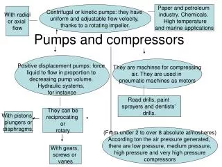
Pumps and Pumping Theory. Pump. PUMPS. Based on PUMPING ACTION. Based on ORIENTATION. Based on NO. OF STAGES. Based on TYPE OF SHAFT SEALING. GLAND PACKING. MECHANICAL SEAL. VERTICAL. HORIZONTAL. Based on Speed Variability. SINGLE STAGE. MULTI STAGE. POSTIVE DISPLACEMENT. DYNAMIC.

E N D
PUMPS Based on PUMPING ACTION Based on ORIENTATION Based on NO. OF STAGES Based on TYPE OF SHAFT SEALING GLAND PACKING MECHANICAL SEAL VERTICAL HORIZONTAL Based on Speed Variability SINGLE STAGE MULTI STAGE POSTIVE DISPLACEMENT DYNAMIC CENTRIFUGAL AXIAL Based on Location Based on PORTABILITY Fixed Speed Variable speed ROTARY RECIPROCATING Based on Prime mover PORTABLE (Wilden, Oil Transfer etc.) FIXED DIAPHRAGM PISTON/PLUNGER GEAR SCREW ENGINE ROOM CARGO SPACE OTHER SPACES Steam Reciprocating Mechanism Diesel Engine Compressed Air Electric Motor Steam Turbine Hydraulic Motor
Classification of Pumps Based on Drive, pumps may be • Electric Motor Driven • Steam Turbine Driven • Steam Reciprocating Mechanism Driven • Compressed Air Driven • Diesel Engine Driven • Hydraulic Motor Driven
Centrifugal pump characteristics • The effects of throttling discharge valve on discharge pressure, efficiency, power and npsh can be seen. The throughput of a centrifugal pump alters with discharge head or back pressure. A slow rate of discharge by a centrifugal cargo pump can be, explained by increasing head due to a restricted or very long discharge pipe, high viscosity of the liquid, discharge to a storage tank sited at a high level or even a partly open valve on the discharge line. Depending on application, centrifugal pumps can be designed with relatively flat H/Qcurves or if required the curve can be steep to give a relatively large shut-off head. We can see from the power curve, that minimum power is consumed by the pump when there is no flow and when the discharge head is at its highest. This equates to the discharge valve being closed. Because maximum pressure with the discharge closed is only moderately above working pressure, a relief valve is not necessary for a centrifugal pump. It will be noticed that the efficiency curve for the pump is convex which means that maximum efficiency occurs at a point somewhere between maximum and minimum discharge head and throughput conditions.
Rotodynamic pumps (or dynamic pressure pumps) • In thisa tangential acceleration is imparted to the fluid. Depending upon supply head they may require a positive displacement pump as a priming device. In general they would be used for medium to high discharge rates, they usually are confined to low viscosity fluids and generate only low to moderate pressure differentials.
Kinetic Pumps (Roto-dynamic)Centrifugal Pumps • Rotation of a centrifugal pump impeller causes the liquid it contains to move outwards from the centre to beyond the circumference of the impeller. The revolving liquid is impelled by centrifugal effect. It can only be projected into the casing around the periphery of the impeller if other liquid in the casing can be displaced. Displaced liquid in moving from the casing to the delivery pipe, causes flow in the discharge side of the system.
Centrifugal Pumps • The liquid in the impeller and casing of a centrifugal pump is also essential to its operation. In moving out under the influence of the centrifugal effect, it drops the pressure at the centre, to which the suction or supply pipe delivers the liquid to be pumped. The moving liquid acts in the same way as a reciprocating pump piston on its suction stroke. Provided that a centrifugal pump is filled initially with liquid and that flow is maintained, the suction stroke action will continue. If such a pump contains no liquid initially, it is as though an essential part is missing.
Types of centrifugal pumps • The volute pump is so called because of the shape of the casing. The object of the volute is gradually to reduce the velocity of the water after it leaves the impeller, andso convert part of its kinetic energy to pressure energy. For general purposes the volute pump is commonly used. In some pumps, diffusers are used. These consist of a ring of stationary guide vanes surrounding the impeller, the passage through the diffuser vanes is designed to change some of the velocity energy in the fluid to pressure energy. The design is used for high pressure as in multi-stage boiler feed pumps. The diffuser passages are able to convert a larger amount of the kinetic energy of the liquid as it leaves the impeller into pressure energy. A single stage diffuser pump is able to deliver to a much greater head than an ordinary volute pump. The regenerative pump is used where a relatively high pressure and small capacity are required.
Centrifugal pump characteristics • The effects of throttling discharge valve on discharge pressure, efficiency, power and npsh can be seen. The throughput of a centrifugal pump alters with discharge head or back pressure. A slow rate of discharge by a centrifugal cargo pump can be, explained by increasing head due to a restricted or very long discharge pipe, high viscosity of the liquid, discharge to a storage tank sited at a high level or even a partly open valve on the discharge line. Depending on application, centrifugal pumps can be designed with relatively flat H/Qcurves or if required the curve can be steep to give a relatively large shut-off head. We can see from the power curve, that minimum power is consumed by the pump when there is no flow and when the discharge head is at its highest. This equates to the discharge valve being closed. Because maximum pressure with the discharge closed is only moderately above working pressure, a relief valve is not necessary for a centrifugal pump. It will be noticed that the efficiency curve for the pump is convex which means that maximum efficiency occurs at a point somewhere between maximum and minimum discharge head and throughput conditions.
Variable speed centrifugal pump • In the case of a variable speed pump: • Head varies as the square of the speed. • Capacity varies directly as the speed. • Power varies as the cube of the speed since it is a function of head and capacity.
Construction of Centrifugal pumps • Double eye Single eye
In single stage pumps a single impeller rotates in a casing of spiral or volute form and in multistage pumps two or more impellers are fitted on the same shaft. Fluid enters the impeller axially through the eye then by centrifugal action continues radially and discharges around the entire circumference. In double inlet pumps fluid enters from two sides to the impeller eye as if there were two impellers back to back giving twice the discharge at a given head. In multi-stage pumps the fluid from one impeller is discharged via suitable passages to the eye of the next impeller so that the total head developed (or discharge pressure) is the product of the head per stage and the number of stages, such a pump is often used for high pressure discharge at moderate speed (e.g. turbo-feed).
The casing usually has the suction and discharge branches arranged at the back so impeller and spindle can be removed from the front without breaking pipe joints. The number of impeller vanes is not ‘fixed but usually there are six to ten. The volute casing is like a divergent nozzle which is wrapped around the impeller and serves two main functions (1) it enables velocity energy to be converted into pressure energy, the degree of conversion is governed mainly by the degree of divergence (2) it accommodates the gradual increase in quantity of fluid that builds at discharge from the circumference of the impeller.
For the velocity to be constant the volute is made so that cross sectional pipe area increases uniformly from cut water to throat. With an impeller having six vanes then the cross sectional area of volute at No. 1 vane will be 1/6th of throat area as one vane is pumping 1/6th of the water quantity, similarly 1/3rd at No. 2 and so on, taking vanes in turn from cut water to throat. A common fault for repair with these pumps is the increase of clearance due to wear at the wearing ring (or sealing ring) faces. This allows connection between suction and discharge so drastically reducing efficiency. During overhaul, the wear ring clearances are checked and if clearances are more than recommended values, than they are renewed.
VERTICAL, SINGLE INLET, CENTRIFUGAL PUMP • Marine pumps are usually installed with the shaft vertical and the motor above the pump. This positions the pump as low as possible for the best NPSH, takes up the least horizontal space and leaves the electric motor safer from gland or other leakage
Shaft sealing • In the smaller pumps the shaft gland seal is by water cooled ordinary stuffing box. Stuffing box type glands may be packed with soft packing. Great care must be taken on these packings as they are very prone to nip and score the shaft severely if not properly adjusted.
Mechanical seal • This consists of a fixed clamp ring on the shaft driving another ring cup, with packing rings on to the shaft, through driving pins. Ring cup and rings are free to slide along the shaft under the action of axial springs from the clamp ring. The cup ring presses on to a fixed ball ring which in turn sits in a ball socket joint in the back plate which bolts to the pump casting.
Centrifugal Pump – Theory and Characteristics Centrifugal pumps are generally used for movement of large volumes of liquid at low pressures. Higher pressures can be obtained with multistaging
A separate pipe from the suction pipe of the main pump is taken to a rotary air pump which is directly driven by a friction clutch operated spindle as shown. The rotor revolves in a special variable shaped chamber which is supplied with fresh water from a separate water tank attached to the air pump casing. The discharge pressure of the pump places the air pump in or out of operation by hydraulic pressure clutching in/out the operating spindle of the air pump.
WATER RING AIR VACUUM PUMP PRINCIPLE • As the impeller vanes pass the suction port air is drawn in and trapped between the water ring and the pump shaft. This ‘slug’ of air is carried around and delivered to the discharge port, hence this pump is a positive displacement type. Due to the casing shape the water is made to flow from and towards the rotor centre during each revolution. The water motion is utilised to act as suction and discharge for the air through appropriate sets of ports.