STAR TU, simulation status
210 likes | 364 Views
STAR TU, simulation status. N. Smirnov Physics Department, Yale University, STAR Collaboration Meeting, MIT, July, 2006. What does mean STAR TU ?. Conserve / Improve TPC performance ( RHIC II Luminosity). High resolution Vertex Detector ( heavy quark Physics ).

STAR TU, simulation status
E N D
Presentation Transcript
STAR TU, simulation status N. Smirnov Physics Department, Yale University, STAR Collaboration Meeting, MIT, July, 2006
What does mean STAR TU ? • Conserve / Improve TPC performance ( RHIC II Luminosity). • High resolution Vertex Detector ( heavy quark Physics ). • “special” tracking in EEMC “direction” ( pp W e+/- ). • Tracking data for PMD ( |η| > 2.); pp, dA • μ– detector (?)
Conserve / Improve TPC performance ( RHIC II Luminosity). • Additional tracking / calibration detectors inside and outside of TPC • Pad or XY strip GEM Detectors is a good choice : • Required 3d- precision • low mass, • fast. • Solves TPC space charge distortions correction problem {“charge” value / number of hits as a F ( t, φ, z); model (can/should be different for pp and AA); correction on “track level”} • and part of tracking (large surface to be covered, R~35 cm). • Together with other “fast” detectors, help to solve the “Event pile-up” problem. • TPC its own improvements; IFC shielding; “gap” between sectors; OFC gas leak membrane HV, CF4 gas mixture smaller diffusion, faster drift (new FEE, on-line cluster finding/reconstruction). Gas amplification calibration • TPC MWPC data: number of tracks in drift volume, tracking for |η| > 1.
High resolution Vertex Detector ( heavy quark Physics ). • Today (HFT) proposal relays on: -- perfect TPC space charge distortions correction (not in a simulation), -- perfect SSD performance ( does not work still, and …), -- perfect alignment, -- factor X improvement in APS read-out speed (X = 2 ?, 2 ms / frame), -- primary vertex is a “key factor”, -- D reconstruction efficiency and background – two different simulation steps, -- APS simulation (N of hits / frame and their position) is not a “realistic” one -- unknown beam-beam background conditions for small R. R&D “step” to demonstrate “hit – track” matching was not done, but in a schedule. • It is too optimistic (my opinion) • Natural limitations: high multiplicity events to get a primary vertex with “needed” precision ( multi-loop approach can help ?) • Conclusion: needs a high precision, fast “pointer” ( SVT was a “candidate”, but ...) The best: 3 points in space to be “independent” from TPC data.
A lot of simulation results have been presented during last STAR Upgrade meeting (December 1-2,2005) • Some conclusions: • - fast, high precision, low mass tracking detectors in front and behind TPC ( GEM) can be crucial to help with TPC “space charge distortions correction”. • - HFT with 4 ms read-out time will work in a combination with TPC+SSD+(GEM) up to L=1x1027, but not a RHIC II Detector. • - IT has to provide a high quality “search corridor” for HFT to “help” with occupancy, primary vertex reconstruction, PP, dA, ….; • - three double layers Si strip detector (MIT proposal) is not the best solution. • - tracking detector in front of EEMC is useless for We+/- + X study because TPC end-cap material budget. • - IT has to solve this problem: high Pt particle reconstruction in EEMC acceptance. Three possible variants for IT (personal opinion) - 3 or 4 double layers of Si strip detectors; first and last – with 90 deg strip direction rotation, and to use pad detectors ( with 2x2 mm2 size) instead of stereo ones for 2 intermediate layers (Gerrit’s idea). - microTPC with fast, low diffusion gas mixture and MicroPattern read-out (no gating grid) - Two layers of Pixel Hybrid Detectors with pad size 50 x 425 μm2
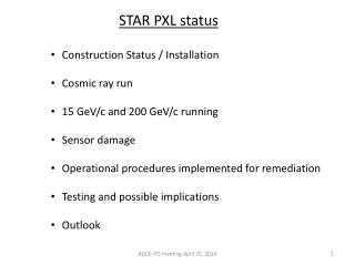
Variant with Si Pixel Det., SPD + Si strip + GEM (III) TPC “IN field-cage” “safety” Kapton foil GEM with X-Y read out SSD Si strip, 4x4 cm2 two layers, X and Z SPD (Hybrid Pixel) Two layers with 90 deg rotation HFT SPD – Design Parameters (ALICE) Two barrel layers; R1 = 6.4 cm, R2 = 7.6 cm. Pixel Cell: 50(rφ) x 425 (z) μm2, (90 deg rot. second layer) Pixel ASIC thickness: <=150 μm. Si sensor ladder thickness: <=200 μm. “Bumps” technology. Cooling: water / C6F14/ [C3F8 (evaporative)] Material budget (each layer): 0.9%X0 ( Si – 0.37, Cooling – 0.3, Bus – 0.17, Support – 0.1 )
Variant I – 4 Double Si strip/Pad1st – 2x2 cm2 (X/Z); 2nd – 4x4 cm2(X/Pad); 3rd – 4x4 cm2(X/Pad); 4th – 4x4 cm2(X/Z) GEM Detectors TPC in field cage SSD Si Strip HRVD
Simulation / Reconstruction approach • Stand – along routines (FORTRAN) on the basis of personal experience and knowledge from previous experiments and R&D activities • Special for fast (but reliable) test / checking different detector SetUps including PiD (dE/dX, Ch.Det., RICH, TRD) and secondary Vertexes finding/reconstruction. • GEANT-3 (GSTAR) • Detector response simulation – 4 variants: -- GEANT hits, but not GSTAR variants (sometimes) -- Gaussian smearing -- “intermediate” scale simulation ( to save a compute time) -- “full” scale simulation ( check Hans Bichsel web page) • Two variants of a “helix fit” • Keep all needed “pointers” for evaluation / control
One particle (π+) /event. Hits in a fit - only IT detectors (primary vertex – OFF); 100% efficiency, perfect alignment. Variant III Matching performance: IT track crossing position – 2nd HFT layer hit (Local CS). Pt, GeV/c dX, cm dX, cm dZ, cm Here it will be presented the simplest, “first step” simulation results: “one π/event”, GEANT hits with Gaussian smearing
Matching performance: track crossing point – HFT L2 hit position (LCS) Set Up Variant: TPC + SSD, Vertex in FIT;All hits Lines – Sp.Ch. effect GEM + SSD + 1 double SiStrip + 2 Si Pixel; ITH SSD + 2 Si Pixel; All hits SSD + 1 Si Pixel; All hits σ of Gauss fit, cm GEM + SSD + 2 Si Pixel; ITH GEM + SSD + 1 Si Pixel; ITH GEM + SSD + 2 double Si strip/pad + 2 Si strip XZ ( MIT proposal)mod, ITH GEM + SSD + 3 double Si strip/pad ( MIT proposal), ITH dZ dX “ITH” – only IT hits are in Fit, “All hits” -- + TPC hits. Vertex OFF
Matching performance: track crossing point – HFT L2 hit position (LCS) Set Up Variant: TPC + SSD, Vertex in FIT;All hits Lines – Sp.Ch. effect GEM + SSD + 1 double SiStrip + 2 Si Pixel; ITH SSD + 2 Si Pixel; All hits SSD + 1 Si Pixel; All hits σ of Gauss fit, cm GEM + SSD + 2 Si Pixel; ITH GEM + SSD + 1 Si Pixel; ITH GEM + SSD + 2 double Si strip/pad + 2 Si strip XZ ( MIT proposal)mod, ITH GEM + SSD + 3 double Si strip/pad ( MIT proposal), ITH dZ dX “ITH” – only IT hits are in Fit, “All hits” -- + TPC hits. Vertex OFF
Variant “Pixel” - 1 or 2 (with 90 deg rotation) layers of SPD (ALICE, LHCB, PHENIX) Variant “3Si2” – 3 Double Si strip/Pad1st – 2x2 cm2 (X/Z); 2nd – 4x4 cm2(X/Pad); 3rd – 4x4 cm2(X/Pad) “Special Variant” for detector response simulation; TPC, GEM, SSD – gaussian smearing SPD, Si-strip / pad – “intermediate”, q with noise, but no FEE , no cross-talk,… APS – Yes/No but realistic read-out and background hits simulation / reconstruction ( 640x640 pads, 30x30 μm2 size, 4 read-out ports, 50 MHz read-out frequency 2. ms read-out time )
Si detectors, number hits (Central HJ) PIXEL 3Si2 Number of tracks that “contributed” in reconstructed hit R pos 6.4 7.6 6.4 11. 16. cm Det. Size 1.74 4. 16. cm2 Strip/pad 0.0002125 0.02 0.04 cm2 N hits (8, 3) (7, 2) (18, 7) (20, 7) (17, 4) ( max, aver) N “destroyed” hits because occupancy ~0.3% ~ 15% 3Si2 PIXEL
Tracks finding / reconstruction (Vertex OFF)( TPC SSD Si…) DCA, XY, cm PIXEL 1 2 3Si2 Eff: 0.8 0.7 0.7 Ghost: 0.064 0.046 0.4 Track DCA parameters Red: all tracks 3Si2 variant Blue: good one, 3Si2 variant Black: all tracks PIXEL variant DCA, Rz, cm
Primary Vertex reconstructionTPC + SSD + PIXEL (1 or 2) PIXEL 2 PIXEL 1 DCA, xy, cm DCA, Rz, cm N of event N of event
APS, number hits L = 2.x10**26, L1, 2 ms read-out time; Nmax hits / det event = 79 Naver = 42 L = 2.x10**27, L1 (2.8 cm R) - ( 815, 314), L2 (4.6 cm) – (284, 135) (max, aver) (max, aver) N hits (L1) Y, cm One detector, reco hits plus background Central HJ N detector X, cm
Tracks finding / reconstruction (Vertex OFF)( TPC SSD PIXEL (1 or 2) APS) Very preliminary Luminosity PIXEL 1 2 2.x10**26 Eff 0.625 0.6 Ghost 0.016 0.013 2.x10**27 Eff 0.65 0.6 Ghost 0.05 0.11 DCA track parameters to Primary vertex Detector combination DCA, xy, μm DCA, Rz, μm (sigma) APS only ---------- 28. SSD + APS 39. 39. PIXEL 1 + APS 71 32 SSD + PIXEL 2 + APS 28 33 All hits 53 91
What is the reason for GEM D ? -- not to use TPC hits (can be strong distortions) for the “final” step – to match track with APS hits, and vertexes (both primary and secondary ) finding and reconstruction -- the best “tool” to struggle with TPC hits space charge distortions, as a scaller and high precision tracker. -- help with events pile-up problem -- may be the first step – use one CTB slat for fast, precision tracking detector behind TPC. • Data from TPC before (in time) a trigger signal -- scaller data -- coordinate inform for particles in EEMC acceptance • SSD <----> two layers of Si strip ( if it will be any problem or timing will be a “stopper” point) in a combination with GEM D. • Tracking in EEMC direction to study pp W e-/+ (next slide)
IT set up -- asymmetric (in Z); Two more layers of Si strip detectors ( one side, 4x8 cm2) to cover “EEMC direction”, for pp program. pp, √s=500, PYTHIA Pt, GeV/c 60. “barrel” position; NOT “disk” 30. η 1. Sample of events, We(μ) + X
Track reconstruction performance.One π+ / event; HFT + IT + minimum 6 TPC hits; perfect alignment η 30 % dPt/Pt dPt/Pt The reconstruction “chain” has to work well; TPC track EEMC cluster electron E electron P (HELIX Radius) matching hits from IT constraint Refit electron charge (+/-)
Points to be discussed • SSD status / performance / future • GEMD; fast, reliable gas detector, COMPAS experience, 10x10 cm2 active size, XY data with q-selection power and “scaler” data to solve TPC sp.ch. distortions corrections on a “track” level (?); man-power support (MIT, Yale); needs “some R&D” ( low mass construction approach, FEE); good progress with foil mass-production. • Si one sided strip detector: does not need R&D, reliable and good tested technology, SSD substitution and EEMC direction (pp); man-power support (MIT) • Si pixel detector: the best way (my opinion) to get in STAR very powerful and reliable Vertex Detector; mass-production is in a progress and a lot of such detectors will be installed in nearest future (ALICE, LHCB, PHENIX). It is crucial to be “in a line” and keep a control and get an experience (can LBL takes a care?) One layer will help a lot (special for 2. ms read-out variant); it means ~490 sensors (<2. M$), but man-power, experience, DAQ,… are very difficult points. • Very crucial – to prepare and control a “global” mechanical structure for IT and HFT (together!!) as a one construction part. Alignment problem can be very difficult to get a high precision tracking data, and it should be flexible for different variants of IT setup(s). • STAR tracking is a “not easy” problem, and needs (may be) nonstandard decisions. It should be a “one person supervision” approach, with high “KEAL” factor, like HHW did a job for TPC