Download
1 / 1
30 likes | 243 Views
6 Amp 230 Volt Supply. 6 Amp 230 Volt Supply. RBC-RD6 PANEL. RBC-RP1 REPEATER PANEL OPTION. 2 Core 0.75mm². RBC-RD6 Wiring Diagram . Located In Header Outdoor Unit (See Component Wiring Diagram). Pressure Sensor. Each Sensor Requires 2 Core 0.75mm Cable (Max Length 12 Meters).

E N D
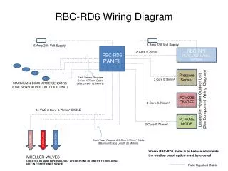
6Amp 230 Volt Supply 6Amp 230 Volt Supply RBC-RD6 PANEL RBC-RP1 REPEATER PANEL OPTION 2 Core 0.75mm² RBC-RD6 Wiring Diagram Located In Header Outdoor Unit (See Component Wiring Diagram) Pressure Sensor Each Sensor Requires 2 Core 0.75mm Cable (Max Length 12 Meters) 3 Core 0.75mm² MAXIMUM 4 DISCHARGE SENSORS (ONE SENSOR PER OUTDOOR UNIT) PCM02E ON/OFF 3 Core 0.75mm² 24 VAC 3 Core 0.75mm² CABLE PCM02E MODE 2 Core 0.75mm² LIQUID DISCHARGE SUCTION Each Valve Require A 3 Core 0.75mm² Cable (Maximum Cable Length 25 Meters) Where RBC-RD6 Panel is to be located outside the weather proof option must be ordered MUELLER VALVES LOCATED IN MAIN PIPE RUN JUST AFTER POINT OF ENTRY TO BUILDING NOT IN CONDITIONED SPACE Field Supplied Cable