Bugeye Wiring
50 likes | 230 Views
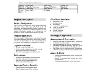
Bugeye Wiring. The original wiring on an unmodified car was marginal with a generator and only 2 fuses. The lights are problematic due to the ground connections that are strung together with bullet connectors. Then add an electric fuel pump and higher power lights and it gets more fun.

Bugeye Wiring
E N D
Presentation Transcript
Bugeye Wiring • The original wiring on an unmodified car was marginal with a generator and only 2 fuses. The lights are problematic due to the ground connections that are strung together with bullet connectors. Then add an electric fuel pump and higher power lights and it gets more fun. • The main upgrades I have planned are relays for the high current devices and convert to alternator charging. I broke the system into 6 main circuits that are each fused: • Headlights • Brake lights • Horn • Lighting • Parking Lights • Gauge Lights • Key Switch • Ignition • Fuel pump • Flashers • Wipers • Heater • Tach • Fuel Gauge • Power Port • The following page shows a state table that defines what should be powered for each combination of the key switch and light switch. Each state is controlled by relays.
Functional Wiring Switch States Defined Ignition Switch B = Battery S = Parking Lights H = Headlights I = Ignition Even thought there is only one switch, The key independently controls the ignition (I) and the lights are either parking (S) or headlights (H) HORN BRAKE LIGHTS 12V AUX • S Ignition Fuel pump Flashers Wipers Heater Tach Fuel Gauge • H • I I BATT + • B Parking Lights Gauge Lights S HEADLIGHTS (LOW) H HEADLIGHTS (HIGH)
Wiring Diagram FLASHER/SIDE LAMP HEADLAMP HEADLAMP FLASHER/SIDE LAMP + - HIGH LOW H FLASHER LAMP DASH LAMP FLASHER SWITCH FLASHER RELAY WIPER SWITCH WIPER MOTOR STARTER SWITCH HORN BUTTON DISTRIBUTOR FUEL PUMP STARTER IGN COIL HORN TANK STOP LAMP SWITCH DIP SWITCH HORN I BRAKE IGN/LT SWITCH ALTERNATOR OIL/WATER SPEEDO TACH FUEL L L L L 2 I B T S B H T B 1 IGN S HI B ACC 50Ω LICENSE PLATE LAMP FLASHER LAMP STOP & TAIL LAMP STOP & TAIL LAMP FLASHER LAMP
Circuit Descriptions + - Charging With an alternator conversion, the charging circuit becomes simple. I chose a standard GM (10-SI, 12-SI) 3 wire internally regulated alternator. These are widely available since there were used on most GM cars and light trucks in the 70’s and 80’s. Terminal-B is the battery terminal and connects directly to the battery for charging. Terminal-1is the field excite/warning light indicator input. This one needs 12V to initiate charging. A light bulb can be put in series to serve as a warning light. The warning light will illuminate if the ignition is turned on and the alternator is not supplying enough voltage. The resistor is a backup to maintain charging if the bulb burns out. HIGH IGNITION LIGHT LOW 50Ω H IGNITION DIP SWITCH Terminal-2 is the remote sense input. It should be run back to the batter or fuse box. This will regulate the voltage at the battery rather than the voltage at the alternator. More details on this here IGN/LT SWITCH ALTERNATOR 2 I B S H 1 Headlights Headlights draw up to 65w each which equals about 11 amps for the pair. Relays are a better option than running that current though the light switch and the dip switch. I chose to have the “H” relay drive the relays for the LOW and HIGH beams. When the lights are turned on current passes through the NC contacts of “H” and energizes the low beam relay. If high beams are requested by the dip switch, “H” moves to the NO position turning off the low beams and turning on the high beams. B