Download

1 / 22
240 likes | 481 Views
Codan C-Band & Ku-Band IF Transceiver Systems. HiSeasNet Training Course. C-Band & Ku-Band Transceiver Systems. Overview The C-Band Systems are labelled the 5700 series. The Ku-Band Systems are labelled the 5900 series.

E N D
Codan C-Band & Ku-Band IF Transceiver Systems HiSeasNet Training Course
C-Band & Ku-Band Transceiver Systems Overview • The C-Band Systems are labelled the 5700 series. The Ku-Band Systems are labelled the 5900 series. • Both C-Band & Ku-Band systems have four major components. Theses components are: • Power Supply • Converter Module • Solid State Power Amplifier (SSPA) • LNA (C-Band) or LNB (Ku-Band) • Power Supply – Receives AC power from the ship and converts it to 48 VDC to power the Converter & SSPA modules. The AC input is switch selectable for either 220 VAC or 110 VAC • Converter Module - The Converter Module performs multiple functions. It provides the interfaces between the below decks equipment (modem & DAC) and the SSPA. Power levels, attenuation levels, and frequencies are programmed in this module using either a PC or hand held controller. It controls the SSPA functions and displays fault conditions. It performs the frequency up conversion from 70 MHz to either C-Band or Ku-Band and the down conversion from C-Band or Ku-Band to 70 MHz
C-Band & Ku-Band Transceiver Systems • Solid State Power Amplifier (SSPA) – The SSPA receives DC power and the Transmit input frequency (C-Band or Ku-Band) from the Converter module. Also, any fault conditions will be relayed to the Converter where it will be displayed on the front panel window. • LNA & LNB – Provides the C-Band (LNA) or Ku-Band (LNB) signal to the Converter module for down conversion to 70 MHz.
C-Band & Ku-Band Transceiver Systems Serial Communications Monitor & Control • The Converter module is configured in two different ways. They are: 1. Remotely connecting a PC running Hyper Terminal using the Seatel Supplied cable. 2. Directly connecting the PC to the Converter using the supplied Codan cable. • The Hyper Terminal setup communication parameters are: 9600 baud, 8 data bits, 1 stop bit , no parity, no hardware control, no flow control • The remote connection is established using the available connector (labeled “RS232”) on the interconnect cable at the back of the DAC. This cable is supplied by Seatel • The direct connection is established using the supplied Codan cable that is normally located with the Spare Parts Kit.
C-Band & Ku-Band Transceiver Systems • Typical Block Diagram for both C-Band & Ku-Band Transceiver Systems
Transceiver Connections - Front Panel For Both the C-Band & Ku-Band Systems the Converter Modules have the same Front Panel Connections. These connections include: RX IF Output (70 MHz signal to modem) TX IF Input (70 MHz signal from modem) Monitor & Control Connector DC Power Input from Codan Power supply Control Panel shows status for Power, SSPA state, and Fault conditions
Transceiver Connections - C-Band Rear Panel • The C-Band & Ku-Band Systems Converter Modules have similar Rear Panel Connections. These connections include: • TX RF Output – Upconverted C-Band or Ku-Band signal sent to SSPA • RX RF Input Signal - LNA (C-Band) or LNB (Ku-Band) • SSPA DC voltage and control signals to amplifier • *C-Band Converter units have an LNA DC/Alarm connector. The Ku-Band Converters do not.
Transceiver Connections - Ku-Band Rear Panel • The C-Band & Ku-Band Systems Converter Modules have similar Rear Panel Connections. These connections include: • TX RF Output - C-Band or Ku-Band signal sent to SSPA • RX RF Input Signal - LNA (C-Band or LNB Ku-Band) • SSPA DC voltage and control signals to amplifier • *Ku-Band Converters have a separate RX L-Band output. The C-Band Converters do not. • The RX L-Band Output is used mainly in combined Transmit/Receive & TVRO systems. This is the full 500 MHz receive band of the satellite
Transceiver Connections - Front Panel Window POWER OFF / STANDBY / ON switchWhen in STANDBY, only the reference oscillator and M&C sections operate. The 5700 or 5900 converter can be turned ON by the control-panel switch, a serial data command or a remote contact closure. • SSPA - INHIBIT / REMOTE / ACTIVATE The Control Panel switch allows local activation or de-activation of the SSPA for maintenance, and for re-setting alarms. Remote control is also possible by serial data command or a dry-contact closure • The highlighted switch positions correspond to: RS232 interface,ASCII protocol, 9600 bits/sec.,8 data bits, no parity. • The TERM and PACKET ADDRESS switch settings are not relevant.
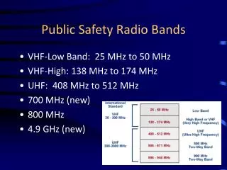
LNA & LNB Specifications • Frequency range • C-Band - LNA 3.400 - 4.200 GHz • Ku-Band - LNB Band 1 10.95 - 11.70 GHz Band 2 11.70 - 12.20 GHz Band 3 12.25 - 12.75 GHz • Gain • C-Band LNA 60 dB • Ku-Band LNB 60 dB • Noise temperature • C-Band 50 K max • Ku-Band 75 K max
C-Band & Ku-Band Transceiver Systems - Frequency Conversions • For both the C-Band (5700) and Ku-Band (5900) Systems: The Converter module accepts 70 MHz input from the SCPC modem (Transmit Path) which it up converts to C-Band or Ku-Band frequencies and sends to the SSPA. The Converter module receives the C-Band or Ku-Band input from the LNA or LNB and down converts them to 70 MHz then sends them to the SCPC Modem. The Local Oscillator (LO) for both C-Band and Ku-Band Converters is not a fixed frequency. It can be adjusted, and is selected in consideration with the satellite RF band to be covered and the frequency range of the modem. This means that the programmed frequency of the Converter is set to the Center Frequency of the specified satellite transponder. This Center Frequency, combined with the frequency range of the modem (+/- 18 MHz) allows the modem to be tuned to a specific frequency within each 36 MHz satellite transponder. The satellite transponder Center Frequency equals the SCPC modem Center Frequency of 70 MHz.
Ku-Band - MBUC RF: 14000 - 14500 MHz IF: 950 - 1450 MHz LO fixed at 15450 MHz Frequency Conversion Examples - Transmit • The following example is based on a HiSeasNet Vessel operating on the Atlantic Ocean Region satellite 6315.545 MHZ Required Transmit RF Frequency as specified by satellite owner/operator 6320.000 MHz Satellite Transponder Center Frequency – Supplied by HiSeasNet Technical Team. Satellite Transponder Center Frequency = Modem Center Frequency of 70 MHz AND Difference between Transponder Center Freq +/- Assigned Freq = Difference between Modem 70 MHz +/- actual required modem frequency Step 1 6320.000 – 6315.545 = 4.455 MHz below modem Center Frequency Step 2 70.000 MHz – 4.455 MHz = 65.545 Required Modem Transmit IF frequency
Frequency Conversion Examples - Receive • The following example is based on a HiSeasNet Vessel operating on the Atlantic Ocean Region satellite Satellite Transmit Frequency - Satellite Frequency Translation = Satellite Receive Frequency 6320.000 MHz - 2225 MHz = 4095 MHz 4090.8525 MHZ Required Receive RF Frequency as specified by satellite owner/operator 4095.0000 MHz Satellite Transponder Center Frequency – Supplied by HiSeasNet Technical Team. Step 1 4095.000 – 4090.8525 = 4.1475 MHz below modem Center Frequency Step 2 70.000 MHz – 4.1475 MHz = 65.8525 Required Modem Transmit IF frequency
Codan 5700 C-Band Commands • 5700 Converter Commands • > VPS • ----------------------Parameter Settings---------------------- • System Command: On Tx Freq: 5850 Atten: 0 • SSPA Activate: On Rx Freq: 3625 Atten: 0 • SSPA Inhibit: Off Cable Comp: 0 • Echo: On Impedance: 50 • Ref. Override: On IF Freq : 70 • SSPA Mode: Extended Faults: LNA - Enable • SSPA Comp Type: 5720-40 FAN - Enable • Conv Comp Type: 5700AVG SSPA - Enable • Packet protocol: Codan Packet addr: 0 (00H) • Power Up: Last State • -------------------------------------------------------------- • For actual transceiver status use VSS command • -------------------------------------------------------------- • > HLP • General Help (this Display) > HLP • Control Commands > HCC • Set Log Commands > HLC • Set Fault enable Commands > HFC • Set Parameter Commands > HPC • View Commands > HVC • Output Commands > HOC • > HCC • System On > SSOn n ==> 0 - Standby 1 - On • SSPA Activate > SPAn n ==> 0 - Off 1 - On • SSPA Inhibit > SPIn n ==> 0 - Off 1 - On • Reset Change Bits > RCB • Reset > RST
Codan 5700 C-Band Commands • > HFC • Set LNA Fault Enable > SLEn n ==> 0 - Disabled ; 1 - Enabled • Set SSPA Fault Enable > SPEn n ==> 0 - Disabled ; 1 - Enabled • Set Fan Fault Enable > SFEn n ==> 0 - Disabled ; 1 – Enabled • > HPC • Set echo > SECn n == > 0 - Off ; 1 - On • Set Ref Override > SROn n == > 0 - Off ; 1 - On • Set Impedance > SIMn n == > 0 - 50 ; 1 - 75 • Set IF Frequency > SIFn n == > 0 - 70 ; 1 - 140 • Set Conv Comp Type > SCTn n == > 0 - Standard; 1 - Custom • Set SSPA Comp Type > SPTn n == > 0 - Off • 1-3 - Custom 1-3 • 4 - 5705 - 5W • 5 - 5710 - 10W • 6 - 5720-40 - 20W/30W/40W
Codan 5700 C-Band Commands • Set SSPA Mode > SPMn n ==> 0 - Extended ; 1 - Basic • Set Tx Frequency > STFnnnn 5850 <=nnnn<= 6425 • Set Rx Frequency > SRFnnnn 3625 <=nnnn<= 4200 • Set Tx Attenuation > STAnn 0 <=nn<= 25 • Set Rx Attenuation > SRAnn 0 <=nn<= 30 • Set Cable Compensation > SCCnn 0 <=nn<= 15 (Disabled) • Set Address Range > SARn n ==> 0 - 0 to 31 • 1 - 32 to 63 • 2 - 64 to 95 • 3 - 96 to 127 • Set Packet Protocol > SPPn n ==> 0 - Codan • 1-3 - Mode 1-3 • Set Power Up > SPUn n ==> 0 - Last State ; 1 - Transmit Off • > HVC • View Faults Status > VFS • View Parameter Settings > VPS • View Control Status > VCS • View System Status > VSS • View Lock Status > VLS • View Identify information > VID • View Table Data > VTD • View System Temperature > VST
Codan 5700 C-Band Commands • > HOC • Output System On > OSO Output Identification > OID • Output SSPA Activate > OPA Output Echo > OEC • Output SSPA Inhibit > OPI Output Ref. Override > ORO • Output Conv Comp Type > OCT Output Temperature Conv > OTC • Output SSPA Comp Type > OPT Output Temperature SSPA > OTP • Output LNA Fault Enable > OLE Output Fault Status > OFS • Output Fan Fault Enable > OFE Output Control Status > OCS • Output SSPA Fault Enable > OPE Output System Status > OSS • Output SSPA Mode > OPM Output Lock Status > OLS • Output Transmit Frequency > OTF Output Transmit Attenuator > OTA • Output Receive Frequency > ORF Output Receive Attenuator > ORA • Output Cable Compensation > OCC Output Fault Logging > OFL • Output Impedance > OIM Output Status Logging > OSL • Output IF Frequency > OIF Output Lock status Logging > OLL • Output Address > OAD Output Temperature Logging > OTL • Output Address Range > OAR Output Packet Protocol > OPP • Output Identity Data > OTD Output Configuration Data > ODP • Output Status Poll > OSP Output Device Type > ODT • Output Frequency Data > OFD Output Compensation Data > OCD • Output Conv Serial No. > OCN Output Power Up > OPU
Codan 5900 C-Band Commands • >HLP • General Help (this Display) > HLP • Set Control Commands > HCC • Set Main Parameter Commands > HPM • Set Auxiliary Parameter Commands > HPA • Set Log Parameter Commands > HPL • View Commands > HVC • Output Parameter Commands > HOP • Output Data Commands > HOD • >HCC • System On > SSOn n ==> 0 - Standby 1 - On • SSPA Activate > SPAn n ==> 0 - Off 1 - On • SSPA Inhibit > SPIn n ==> 0 - Off 1 - On • Reset Change Bits > RCB • Reset > RST • >HPM • Set Tx Frequency > STFnnnnn 14000 <=nnnnn<= 14500 MHz • Set Rx Frequency > SRFnnnnn 10950 <=nnnnn<= 11700 MHz • Set Tx Attenuation > STAnn 0 <=nn<= 25 • Set Rx Attenuation > SRAnn 0 <=nn<= 25
Codan 5900 C-Band Commands • >HPA • Set Receive Range > SRRn n ==> 0 - 950 to 1700 MHz • 1 - 10950 to 11700 MHz • 2 - 11700 to 12200 MHz • 3 - 12250 to 12750 MHz • Set SSPA Mode > SPMn n ==> 0 - Extended ; 1 - Basic • Set Reference Override > SROn n ==> 0 - Off ; 1 - On • Set Cable Compensation > SCCnn 0 <=nn<= 15 (Disabled) • Set IF Frequency > SIFn n ==> 0 - 70 ; 1 - 140 • Set Impedance > SIMn n ==> 0 - 50 ; 1 - 75 • Set LNB Fault Enable > SLEn n ==> 0 - Disabled ; 1 - Enabled • Set SSPA Fault Enable > SPEn n ==> 0 - Disabled ; 1 - Enabled • Set O/P Fault Enable > STEn n ==> 0 - Disabled ; 1 - Enabled • Set Conv Comp Type > SCTn n ==> 0 - Standard ; 1 - Custom • Set SSPA Comp Type > SPTn n ==> 0 - Off; 1 - 59xx Std; 2 - Custom • Set SSPA Detector Type > SPDn n ==> 0 - 59xx Std ; 1 - Custom • Set Output Threshold > SOTnn 20 <=nn<= 55 • Set echo > SECn n ==> 0 - Off ; 1 - On • Set Packet Protocol > SPPn n ==> 0 - Codan ; 1-3 - Mode 1-3 • Set Address Range > SARn n ==> 0 - 0 to 31 ; 1 - 32 to 63 ; 2 - 64 to 95 ; 3 - 96 to 127 • Set Power Up > SPUn n ==> 0 - Last State ; 1 - Transmit Off
Codan 5900 C-Band Commands • >HPL • Set Fault Logging > SFLn n ==> 0 - Disabled ; 1 - Enabled • Set Status Logging > SSLn n ==> 0 - Disabled ; 1 - Enabled • Set Lock status Logging > SLLn n ==> 0 - Disabled ; 1 - Enabled • Set Temperature Logging > STLn n ==> 0 - Disabled ; 1 - Enabled • Set Power Logging > SPLn n ==> 0 - Disabled ; 1 – Enabled • >HVC • View Faults Status > VFS View Identity Converter > VID • View Parameter Settings > VPS View Identity SSPA > VIP • View Control Status > VCS View Table Data > VTD • View System Status > VSS View System Temperature > VST • View Lock Status > VLS View Max/Min Temperatures > VMT • View SSPA Faults > VPF
Codan 5900 C-Band Commands • >HOP • Output System On > OSO Output SSPA Activate > OPA • Output Reference Override > ORO Output SSPA Inhibit > OPI • Output Transmit Frequency > OTF Output Transmit Attenuator > OTA • Output Receive Frequency > ORF Output Receive Attenuator > ORA • Output SSPA Mode > OPM Output Receive Range > ORR • Output Conv Comp Type > OCT Output LNB Fault Enable > OLE • Output SSPA Comp Type > OPT Output SSPA Fault Enable > OPE • Output SSPA Detector > OPD Output O/P Fault Enable > OTE • Output O/P Threshold > OOT Output Fault Logging > OFL • Output Cable Compensation > OCC Output Status Logging > OSL • Output IF Frequency > OIF Output Lock status Logging > OLL • Output Impedance > OIM Output Temperature Logging > OTL • Output Packet Protocol > OPL Output O/P Power Logging > OPL • Output Address > OAD Output Echo > OEC • Output Address Range > OAR Output Configuration Data > ODP • Output Identity Data > OTD Output SSPA Band > OFP • Output Power Up > OPU
Codan 5900 C-Band Commands • >HOD • Output Temperature Conv > OTC Output Max/Min Conv Temps > OMC • Output Temperature SSPA > OTP Output Max/Min SSPA Temps > OMP • Output SSPA O/P Power > OPO Output Identity Conv > OID • Output SSPA Compensation > OPC Output Identity SSPA > OIP • Output Fault Status > OFS Output Device Type > ODT • Output Control Status > OCS Output Frequency Data > OFD • Output System Status > OSS Output Comp/Detector Data > OCD • Output Lock Status > OLS Output Conv Serial No. > OCN • Output SSPA Faults > OPF Output SSPA Serial No. > OPN • Output Status Poll > OSP