Download
1 / 48
480 likes | 611 Views
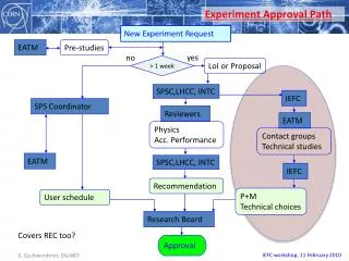
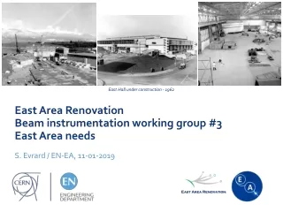
EN. Reorganization of East Area Beam Lines 2 nd Status Report at IEFC Workshop . L.Gatignon, 11/02/2010. OUTLINE:. Motivation Reminder of 2009 conceptual design Constraints from physics programme Contain radiation Magnets available Open questions in 2009

E N D
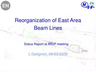
EN Reorganization of East Area Beam Lines2nd Status Report at IEFC Workshop L.Gatignon, 11/02/2010
OUTLINE: • Motivation • Reminder of 2009 conceptual designConstraints from physics programmeContain radiation Magnetsavailable • Open questions in 2009 • UpdateShielding and other RP requirements Controls Costs and resource requirements • Time line • Conclusions Reorganisation of East Area Beam Lines
WHY A NEW LAYOUT FOR THE EAST AREA Triggeredby ABOC/ATC days in 2007 • Splitters lead to high beam losses in critical regions- high radiation levels - no beam loss monitors! • Catastrophic situation of magnets- 63 magnets of 22 different types, many critically weak and/or no spares - need 2 weeks to open & close concrete roof shield + cooldown + repair - space very tight, access extremely difficult - high radiation levels - EA has only 8% of #magnets in NA, but needs same #FTE to maintain • No remote control for most systems (motors in particular)No high level control system, no beam files Grossly insufficient beam instrumentation– somewhat improved since then Recommendation: global review of East Area Note: Operational difficulties with F61N.BVT01 in 2008, T10 only 6 GeV due to two Q800 (smoke traces!), three Q120’s replaced in 2009, … + F61N.DVT01 broken, suspected problems in T7 line, … (2009/2010) Reorganisation of East Area Beam Lines
To liberate PS cycles for DIRAC and still requests being added, due to pressure on beam time! = Tests = CLOUD THE EAST AREA CONTINUES TO BE POPULAR: This trend continues in 2010: 335+80 days requestedin T9,T10,T11 Reorganisation of East Area Beam Lines
BASIC PRINCIPLES FOR NEW EAST AREA • Use fewer types of reliable magnets with spares • Reduce roof shielded areas and ease access to equipment • Keep radiation restricted to upstream areas as much as possible • Keep T8 beam and DIRAC installed as it is until the end of DIRAC,or for IRRAD in case they take over the DIRAC location • Replace SMH1 and F61S.BHZ1 by two MCB magnets in PPM mode,i.e. no more splitter (F61S.BHZ01 replacement already done). • Could also serve IRRAD as now, through air, however not from ZT7.BHZ01but from F61S.BHZ02 • Design new beam(s) to 1 (or 2) “North target” marguerite(s)- two decoupled beams, but at the cost of cycle efficiency - two beams coupled by “wobbling station”, coupled but higher cycle efficiency • Test beams can provide pure hadron and muon secondary beams up to 15 GeV/cand pure (> 95%) electron beams from g conversion (up to about 10 GeV/c) Inspired by and similar in spirit to West Area rebuild in the end of the 1990’s! Reorganisation of East Area Beam Lines
Uses “dummy magnets” ~5x better transmission than present lines! m± pure h± e± Reorganisation of East Area Beam Lines
Not significantly different from 2008 Different central trajectory + changes of magnet types Reorganisation of East Area Beam Lines
SECONDARY BEAM OPTICS FOR “T9++ BEAM” – UP TO 15 GeV/c Reorganisation of East Area Beam Lines Even better transmission than generic optics!
SECONDARY BEAM OPTICS FOR “T10++ BEAM” – UP TO 12 GeV/c Reorganisation of East Area Beam Lines
SCHEMATIC LAYOUT OF THE TWO SECONDARY BEAMS (inspired by “West Area 2000” approach) Reorganisation of East Area Beam Lines
30 mrad prod. angle (vertical) PROTONS DUMPED Reorganisation of East Area Beam Lines
2009 version And this is how it looks ‘on the floor’: Reorganisation of East Area Beam Lines
The shapes are made as overlays on the old, respectively new layout drawing, on the same scales Primary zone Open PS zone DIRAC PS zone Primary zone Open Sec. zone DIRAC Old layout: New layout: Reorganisation of East Area Beam Lines
Proposed layout, 2010 version: Reorganisation of East Area Beam Lines
What does this mean (2009 slide) ? • Compatibility with requirements from DIRAC/IRRAD and CLOUD • More flexible and better test beams, but (effectively <) 1 lessHigher top momenta, small production angles, choice of particle type • Only use agreed ‘healthy’ magnets with sufficient sparesAll magnets and rectifiers exist – reduced cost • Primary beam is dumped almost immediately after targetHigh (also induced) radiation levels restricted to minimal areas • Very restricted number of magnets is under heavy roof shieldingThe ones in a limited zone following the primary area have only a thin roof shield. Many have no roof shielding.RP simulations are required to see whether the latter shield can be avoided • Restricted material cost but lots of reshuffling of lines and shielding Reorganisation of East Area Beam Lines
Questions left open last year • Radioprotection studies to confirm reduction of shielding • Costs, resources- Transport and handling - Magnets and rectifiers + infrastructure - Instrumentation, controls - Vacuum - Radioprotection - ….. • Timeline Reorganisation of East Area Beam Lines
Transport and handling resources Estimate assumes a team of 3 persons Hence required ~ 20 man months Reorganisation of East Area Beam Lines
Cost for rectifiers and magnets: The PO group recommends this even if we do not change the layout On the longer term a more complete consolidation / renovation of the old rectifiersin the East Area will become necessary. A full consolidation might cost ~ 2.8 MCHF. Again, independently of whether the layout is changed or not. Reorganisation of East Area Beam Lines
Courtesy J.L.Blanc Reorganisation of East Area Beam Lines
Courtesy J.L.Blanc Reorganisation of East Area Beam Lines
SHIELDING AND RP ISSUES Primary zone PS zone Primary zone Open Sec. zone DIRAC Carefully studied by Thomas Otto / RP Thickness of shielding 2.4 m (as shown before) Height of walls > 4 m to reduce sky-shine No roof shielding required Optimise access chicane Optimise target design (shielding vs intervention time) OK as it proposed Side shielding thickness 6 to 6.4 m (as now) 2.4 m roof shielding, i.e. 0.8 m Fe + 1.6 m Concrete Need ventilation (cf nTOF target area) Optimise entrance chicane Reorganisation of East Area Beam Lines
Cost of Ventilation Th.Otto requests a ventilation system for the small primary zone, similar to the one implemented for the nTOF target area. This would also evacuate Ozone from the area, which now stays andaffects the equipment in that zone (corrosion of magnets etcetera). Evacuation of the extracted air via the roof of B157 For the cost we quote the cost of the nTOF installation as an example It would probably reasonable to to foresee a ventilation for the primaryarea even if the layout would not be changed Reorganisation of East Area Beam Lines
Cost of Vacuum To be confirmed Reorganisation of East Area Beam Lines
Other Costs *) Based on 2004 estimate in the framework of Renovation Programme Committee Reorganisation of East Area Beam Lines
Side remark (2009 slide): In 2005 a proposal was made to upgrade the controls of the East Area. For the moment in the East Area there is: • no remote control / readout of collimators • control of magnet currents only by working sets and knobs • no easy and convenient beam files • no remote reading of access system and vacuum state • no user applications for reading of beam instrumentationHowever, one delay wire chamber + a scintillator were added per beam since then It seems that this could be an occasion to migrate the East Area controls to Cesar(i.e. the recently upgraded North Area controls). At the time the resource estimate (excluding DWC + scints) were about 80 kCHFfor VME crates + Cerenkov upgrades plus a number of man months on the software side. Now part of this upgrade has been done already (timing, VME). Reorganisation of East Area Beam Lines
Cost of controls upgrade *) Independent of East Area project but considered useful by BE-CO to combine the two Reorganisation of East Area Beam Lines
Summary of costs: Grand total: ~ 1050 kCHF+ ≤ 5 FTE Reorganisation of East Area Beam Lines
Consolidation of East Area recommended independent of this project • Ventilation of primary area would reduce Ozone impact on magnets anyway • Replacement of old rectifiers (R2A and R2) to be considered anywayand of most rectifiers in the not too distant future • Upgrade of controls would be a good thing even in case of no layout change • In the long term migration from ARCON to RAMSES-2 will become necessaryApproximate cost 300 kCHF, foreseen in consolidation project.The migration to Ramses-2 should be kept in mind during the installation workof this project. • The air conditioners are mostly in a pitiful state and need replacement Reorganisation of East Area Beam Lines
Rebuild of parts inside PS and of primary zone in shutdown 2010/11,provided CLOUD has completed its Mk2 program Continue construction of test beams during the 2011 runCould probably continue operation of DIRAC during 2011 withsome additional local shielding at exit of the primary zone Total duration of project: first estimates 8-12 months Proposed time line (2009) 2012+? • CLOUD changes from Mk2 to Mk3 module in 2011 (tbc)This requires a larger beam and a larger zone (T11 → T9B zone)It seems reasonable to synchronize the EA modifications with this change • DIRAC / IRRAD future not well understood at this momentbut new design is essentially decoupled from this question Run in 2010 “certain” Will request run in 2011 (long-lived atoms) 2011/12? Reorganisation of East Area Beam Lines
Taking into account • The timescales of CLOUD and DIRAC as they are known today, • The recent announcements concerning a long LHC run, i.e. (to my understanding) no long shutdown in 2010/11, • That the management is launching studies how to prolong the lifetime of the of the present injector complex (including the PS) byat least another 15-25 years it seems that starting the work end 2011/early 2012 could be aconvenient option. It could then be completed in time for the 2013 start-up The duration of the work has been estimated to be less than one year (9 months), The part affecting PS operation within 4 months Reorganisation of East Area Beam Lines
CONCLUSIONS • The design of a new East Area layout presented at the previous IEFC workshop has been validated (with very minor modifications) in terms of its radioprotection merits • It uses reliable equipment and improves greatly their accessibility and maintainability • The cost is around 1 MCHF + 4-5 FTE, even including some changes which should even be considered if the layout is not changed. • The change can be done within one year, with at most 4 months stop for the PS, andthe year 2012 seems a possible period in terms of the East Area physics prospectsand the latest planning for LHC operation and shutdowns. • A non-exhaustive list has been shown of some items that need further consolidationif the East Area has to be operated for another 15-25 years or more. Reorganisation of East Area Beam Lines
Thanks to all who have helped in preparing this work. Particular mention to: Vito Baggiolini, Yves Bernard, Jean-Luc Blanc, Dominique Bodart, Yannick Body, Jan Hansen, Michael Lazzaroni, Gilles Le Godec, Patrick Lelong, Alessandro Masi, Robert Mollay, Thomas Otto, Jens Spanggaard, Davide Tommasini, Giovanna Vandoni, Markus Widorski, … Reorganisation of East Area Beam Lines
Spare slides Reorganisation of East Area Beam Lines
TURTLE SIMULATION (for C1ACCV=C2ACCH = ±40 mm, C3DP = ±1 mm) Y in mm X in mm Reorganisation of East Area Beam Lines
Dp/p in % Reorganisation of East Area Beam Lines
COMPLETE RECTIFIER CONSOLIDATION – Part I Reorganisation of East Area Beam Lines
COMPLETE RECTIFIER CONSOLIDATION – Part II i.e. cost up to about 2.8 MCHF Reorganisation of East Area Beam Lines
Survey manpower Assume a team of 2 persons Total FTE: 4.2 man months Reorganisation of East Area Beam Lines
From note by Luc Durieu: Reorganisation of East Area Beam Lines
From note by Luc Durieu: Reorganisation of East Area Beam Lines