Download
1 / 27
270 likes | 397 Views
2 nd ILC Accelerator Workshop (Personal Impressions of a Beam Instrumentalist). Manfred Wendt Sept. 7, 2005. http://alcpg2005.colorado.edu/. Seminar on Beam Instrumentation Techniques and Technology. Organization and Statistics. Working Fields: Detector Physics

E N D
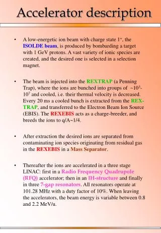
2nd ILC Accelerator Workshop(Personal Impressions of a Beam Instrumentalist) Manfred Wendt Sept. 7, 2005 http://alcpg2005.colorado.edu/ Seminar on Beam Instrumentation Techniques and Technology
Organization and Statistics Working Fields: • Detector • Physics • Accelerator (2nd ILC Accelerator Workshop) • Education and Outreach Participants (1st week): • ≈ 650 total (≈ 80 Fermilab) • ≈ 250 accelerator experts • ≈ 15…20 typical GG/WG attendance
Accelerator Working Groups WG1 LET Beam Dyn. WG2 Main Linac WG3a Sources WG3b DR WG4 BDS WG5 Cavity WG6 Communication Sub-System WG Global Group GG1 Parameters GG2 Instrumentation GG3 Operations & Reliability GG4 Cost & Engineering GG5 Conventional Facilities GG6 Physics Options
1st Week • Plenary Presentations (Mo, Fr) • Parallel Session Talks (Tu, We, Th) 2nd Week • WG Discussions (Mo…Th) • Plenary Presentations (Fr) Special Events • 7x Lunch-Time Seminars • Evening Events, Discussions, Dinner,…
The GDE Plan and Schedule 2005 2006 2007 2008 2009 2010 Global Design Effort Project LHC Physics Baseline configuration Reference Design Technical Design ILC R&D Program Bids to Host; Site Selection; International Mgmt
ILC Goals and Parameters • Ecm adjustable from 200 – 500 GeV • Luminosity ∫Ldt = 500 fb-1 in 4 years • Ability to scan between 200 and 500 GeV • Energy stability and precision below 0.1% • Electron polarization of at least 80% • The machine must be upgradeable to 1 TeV
48 BCD Questions (Himel’s List) 2. Beam and luminosity parameters? 3. SCC “starting” gradient and upgrade path? 4. 1 or 2 IR’s? 5. 1 or 2 tunnels, deep or shallow? 6. DR size and shape? 7. e+ source: conv., undulator, compton? ... 29. How many diagnostic sections in the linac? 33. MPS design? 35. Use structure (HOM) BPM’s? 43. Re-entrant or cavity BPM’s for the main linac?
Global Group 2:Instrumentation & Controls Conveners: Marc Ross (SLAC), Hans Braun (CERN), Junji Urakawa (KEK) Presentations: • S-Band Cavity BPM for ILC Linac, Zenghai Li • Cold Linac BPM’s, Manfred Wendt • Cold BPM Options, Olivier Napoly • Cold Re-entrant BPM, Claire Simon • ILC Cavity BPM’s, Steve Smith • ILC Laserwires, Grahame Blair • Survey and Alignment of ILC, Armin Reichold • Beam Based Feedback Systems, Phil Burrows • High Availability Electronics & Standards for ILC, Ray Larsen • Stabilization of the Final Focus, David Urner
Beam Position Monitors • Cold Linac BPM’s: • 2 x 400 dedicated re-entrant cavity or CM-free cavity BPM’s • 2 x 10000 HOM (structure) monitors for beam displacement (???)
Simple “Pill-Box” Cavity BPM Problems: • TM010 monopole common mode (CM) • Cross-talk (xy-axes, polarization) • Transient response (single-bunch measurements) • Wake-potential (heat-load, BBU) • Cryogenic and cleanroom requirements
CM-free Cavity BPM’s KEK ATF nanoBPM collaboration: • BINP cavity BPM • C-Band (6426 MHz) • 20 mm aperture • Selective dipole-mode waveguide couplers • 3 BPM’s in a LLBL hexapod spaceframe (6 degrees of freedom for alignment) • Dual-downconversion electronics (476 & 25 MHz) • 14-bit, 100 MSPS digitizer
BPM ASSEMBLY BPM struts
Beam Parameters Qbunch≈ 1.5 nC σx≈ 80 µm σy≈ 8 µm σz≈ 8 mm (!) ΔE/E ≈ 5 E-4 Jitter: - σx≈ 20 µm - σy≈ 3.5 µm - σ’x≈ 1000 µrad - σ’y≈ 2 µrad Signal Processing • Digital Downconversion: • Multiply digital waveform by complex “local oscillator” eiwt • Low-pass filter (currently 2.5 MHz B/W) • Sample complex amplitude of position cavity at “peak” • Divide by complex amplitude from reference cavity • Scale/rotate by calibration constants • Refine calibration with linear least-squares fit to other BPM measurements, e.g. y2pred = f(y1,y3,x2) • Removes beam jitter, rotations, cal. errors. • Monopole modes appear as offset in (I,Q) space (as do mixer offsets, rf leakage).
10 minute run • 800 samples • σ≈ 24 nm Move BPM in 1 µm steps
KEK Cavity BPM • Very compact design to save space • Waveguide has fold, asymmetry • Differs from BINP design • BINP BPM has long waveguide taper to coax adapter • KEK coax adapter is very close to cavity
KEK group sees ~ 70 nm resolution • Also X-Y coupling • Monopole mode leakage X2 Y1 Y2 X1
Re-entrant Cavity BPM • Coaxial cavity BPM • Evanescent fields of the TE11 dipole mode • Very low Q ≈ 4 • Cryogenic and cleanroom approved
Improved re-entrant BPM design: • Better to be cleaned (12 holes) • More reliable feedthrough construction • Reduced damping • Qdipole≈ 52 (fdipole = 1.72 GHz) • Qmono≈ 24 (fmono = 1.25 GHz) • Expected single-bunch resolution ~ 1 µm
Q43: Re-entrant or Cavity BPM? Answer: Not yet decided, R&D required! • Re-entrant BPM meets cryogenic and cleanroom requirements, but has limited resolution*. • CM-free cavity BPM meets resolution requirements*, but has to show cryogenic and cleanroom compatibility. * The required single-bunch resolution was set by GG2 to σ/3 ≈ 0.5 µm for diagnostic purposes, WG1 (LET) assumes 1…10µm BPM resolution.
Accelerating Cavity HOM Couplers as BPM (HOM-BPM) • Naturally narrow band cavity : QL ≈ 104 , ≈ 1 µs • single bunch, • but not bunch to bunch BPM • Relative position resolution ~ 4 µm (cf. M. Ross and J. Frisch).
y 5 x 4 2 1 polarization directions 3 Centering accuracy < 40 µm, using a single mode (2 polarisations) Angular scan resolution and accuracy < 50 µrad
High Availability Electronics ATCA Telecom System: A=0.99999 • 2 Control & 12 Applications slots • Up to 200 W/module at 45ºC ambient, 2.8KW Shelf • Redundant speed controlled DC fans Mezzanine Card Option 3x7inch Hot Swappable Up to 8/Mbrd
Personal Impressions • Many beam instrumentation collaborations in progress: • SLAC, KEK, LLNL, LBL, …: nanoBPM’s at ATF • SLAC, DESY: HOM-BPM at TTF • CEA-Saclay, DESY: Re-entrant BPM at TTF • SLAC, DESY: LOLA long. bunch profile at TTF • SLAC, Uni London (QM): Fast IP feedback at the SLAC Linac • Uni London (RH), JAI, DESY: Laserwire trans. profile at PETRA • Very good working atmosphere! • Technology choice (1.3 GHz SC Cavities) accepted! • SLAC seems to me very active(!), not only in the field of beam instrumentation.